
High Precision Voltage-Controlled Oscillator (VCO)
This voltage-controlled oscillator (VCO) circuit is designed to generate stable and precise waveform outputs suitable for various applications, including music synthesis and signal measurement. The core components include an operational amplifier (U1) functioning as a mixer and a Schmitt trigger comparator (U2) that introduces hysteresis to stabilize the oscillation frequency.
The operational amplifier operates in a feedback configuration, where the resistors R3 and R4 set a reference voltage at one-third of the input voltage (Vin). This configuration ensures that the output at pin 6 of U1 oscillates between defined thresholds, determined by the hysteresis set by resistors R6 and R7 in the Schmitt trigger. The switching behavior of the FET (Q1) is crucial, as it acts as an electronic switch that controls the charging and discharging of capacitor C1.
When the FET is turned off, capacitor C1 charges through resistors R1 and R2, leading to an increase in voltage at U1's output. Once the output voltage exceeds the upper threshold of U2, the comparator output switches, turning the FET on and reversing the current flow in C1. This process creates a sawtooth waveform as the capacitor discharges rapidly when SW1 is closed, effectively doubling the frequency of the output waveform.
The circuit's design emphasizes precision and stability, with most resistors specified to have a tolerance of 1% or better, ensuring minimal variation in frequency output. The voltage-frequency conversion rate of 357Hz/Volt indicates the sensitivity of the oscillator to changes in the control voltage, making it suitable for applications requiring precise frequency control. Proper calibration of the potentiometer R11 is essential for achieving the desired output voltage levels, ensuring the circuit operates within specified parameters.
In conclusion, this voltage-controlled oscillator circuit offers a versatile solution for generating multiple waveform outputs with high precision, making it an invaluable component in electronic music synthesis and measurement devices.This voltage-controlled oscillator circuit is very compact and has a good linearity. The author said that the precision could be better than 0. 01% If this circuit is properly constructed. Moreover, this circuit gives three different output waveforms: square, triangle, and sawtooth. This three waveform is important for music synthesizer and measure ment devices. Here is the circuit`s schematic diagram: The oscillator consist of a mixer (U1) and a comparator with hysteresis U2. if U2 has positive output ( 15V) then FET Q1 will be conducting, and if the output is negative then the FET will be open, in other words, the FET will function as an electronic switch.
The voltage at pin 2 U1 will be kept constant at 1/3 Vin (set by R3 R4) by op-amp feedback mechanism. If Q1 is switched off then the capacitor C1 will be charged from Vin to U1 out through R1 and R2. The effect of this charging is that the voltage seen at U1 (pin 6) output will increase. After this pin 6 U1 voltage reach the upper threshold of U2 Schmidt trigger (the hysteresis is set by R6 R7), the U2 output will swing to V and switch on the Q1 switch.
After Q1 switched on, the capacitor C1 current now reverse it`s direction, discharging, and the U1 output will be decreasing. After reaching the lower threshold level of U2 Schmidt trigger then U2 output will swing to V-, switch the Q1 off and the restart the cycle.
The sawtooth output will be a triangle wave with same frequency as the square wave output when SW1 is open. If SW1 is closed then the C1 capacitor discharging will be very fast and the triangle output will change into sawtooth waveform with two times higher frequency.
The amplitude of sawtooth or triangle output will be about ( -) 8. 3V, and the square output will be ( -) 15 V. Except for R5, R9, and R10 those require no high precision, all resistors should be 1% tolerance or better. where the frequency is in Hz, capacitance in Farad, and resistance in Ohm. Vin is the control voltage in Volt. With the values shown in the schematic diagram, the voltage-frequency conversion rate will be 357Hz/Volt.
Setting the R11 potentiometer is done by shorting the negative and positive inputs of U1 to ground and adjust R11 to give zero volt reading at U1 output (pin 6). [circuit `s schematic diagram source: elector] 🔗 External reference
Related Circuits
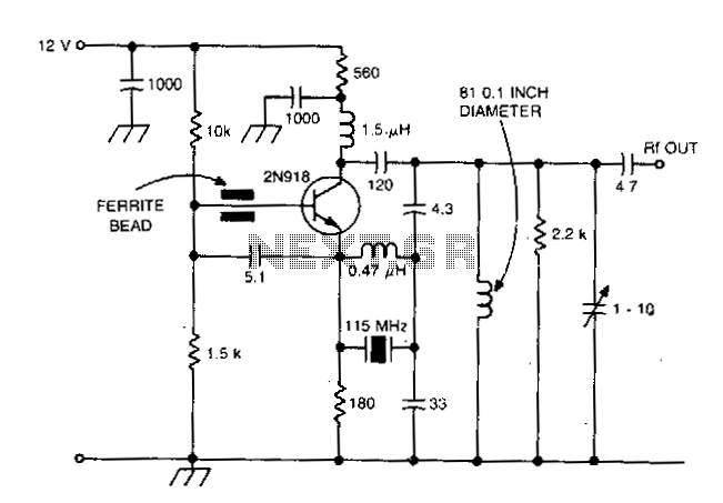
This design is intended for high reliability across a broad temperature range utilizing fifth and seventh overtone crystals. The inductor connected in parallel with the crystal induces antiresonance of crystal capacitance (Co) to reduce loading effects. This technique is...
The MOSFET input of the CA3140 is ideally suited for use in a high impedance DC voltmeter. The range selector is controlled by switch S1. The input impedance is limited to 10M by the resistors in the voltage divider,...
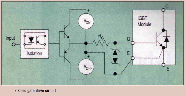
High power IGBT modules utilize hybrid integrated circuit (IC) gate drives that incorporate protection circuits, which implement desaturation detection or real-time control. High power Insulated Gate Bipolar Transistor (IGBT) modules are essential components in various high-efficiency power conversion applications, such...
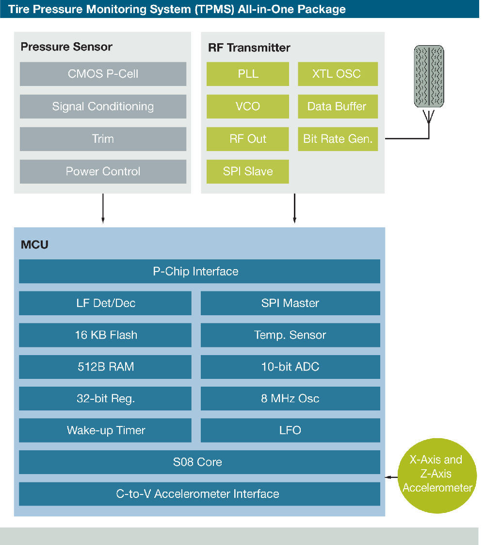
Freescale Semiconductor has introduced what it claims to be the industry's first tire pressure monitoring system (TPMS) featuring a capacitive pressure sensor designed for ultra-low power consumption and precise sensing. "By utilizing capacitive sensor technology, we achieve low power...
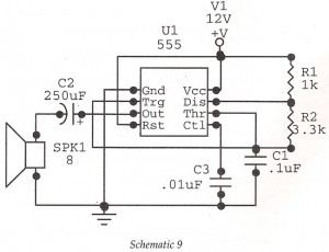
This circuit features an astable oscillator constructed around a 555 timer, generating an alarm tone of 1.8 kHz, which directly drives a speaker. It serves as a fundamental alarm circuit that can be utilized in various projects. Although the...
A high-quality intercom system that can also be utilized for room monitoring. The intercom system described is designed to provide clear and reliable communication between different rooms or areas within a building. It features high-fidelity audio components that ensure minimal...