
1KHz Sine wave Generator

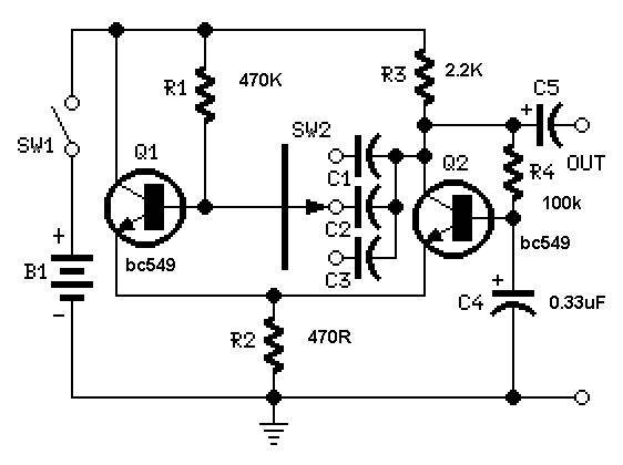
The circuit utilizes an inverted Wien bridge oscillator, which is a well-established method for generating sine waves. The core of the circuit comprises two capacitors (C1 and C2) and four resistors (R3 and R4) configured to create a feedback loop that stabilizes the oscillation frequency at 1 kHz. The use of precision components in the feedback network is crucial for minimizing distortion and ensuring a clean sine wave output.
The variable output feature allows for adjustments in amplitude, which is essential for testing various audio equipment without exceeding their input limits. The low output impedance is significant as it enables the circuit to drive loads effectively, maintaining signal integrity even when connected to multiple devices or under varying load conditions.
Incorporating a small filament bulb serves a dual purpose: it acts as a stabilizing element in the circuit and provides visual feedback on the output amplitude. As the output amplitude varies, the filament bulb's brightness changes correspondingly, allowing the user to monitor the output level easily.
This sine wave generator is particularly useful for testing high-fidelity audio devices, such as the Precision Audio Millivoltmeter and the Three-Level Audio Power Indicator. By providing a stable sine wave signal, the circuit facilitates the evaluation of frequency response, distortion characteristics, and overall performance of audio circuits, making it an invaluable tool in audio engineering and testing environments.This circuit generates a good 1KHz sinewave adopting the inverted Wien bridge configuration (C1-R3 & C2-R4). It features a variable output, low distortion and low output impedance in order to obtain good overload capability.
A small filament bulb ensures a stable long term output amplitude waveform. Useful to test the Precision Audio Millivoltmeter, Three-Level Audio Power Indicator and other audio circuits posted to this website. 🔗 External reference
Related Circuits
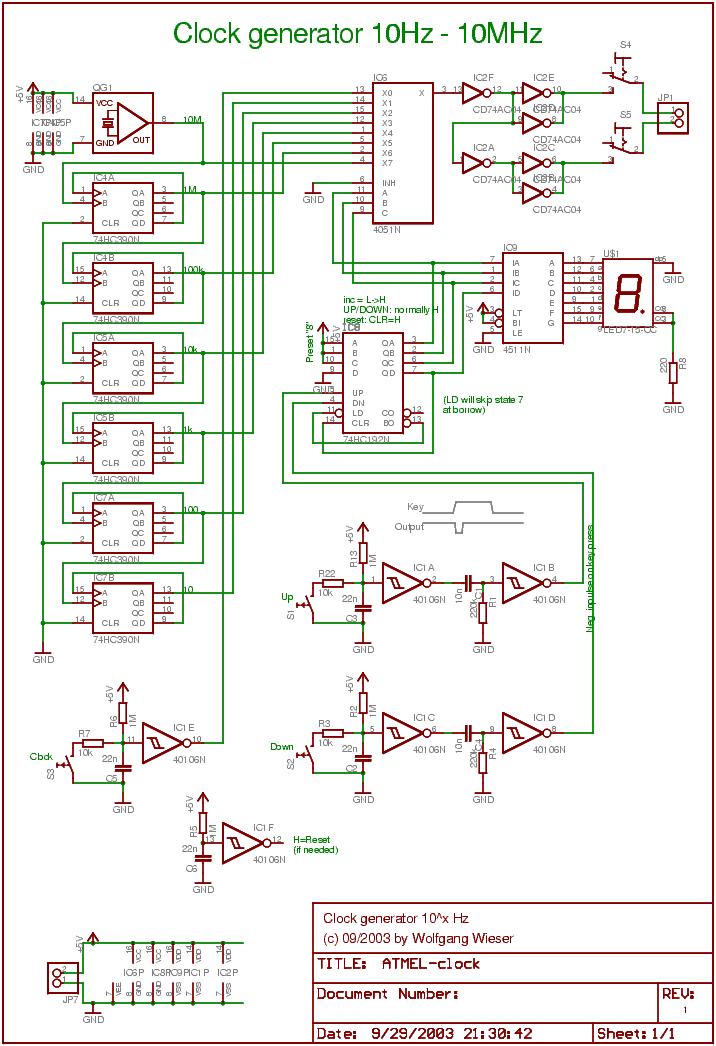
The device described can generate a complementary clock signal at frequencies ranging from 10Hz to 10MHz in factors of ten. It is referred to as the "10xHz clock generator," where 'x' is a number between 1 and 7. Additionally,...
A versatile circuit of an IF signal generator that may be of interest to radio hobbyists and professionals alike. Transistors T1 and T2 form an astable multivibrator oscillating in the audio frequency range of 1 to 2 kHz. An...
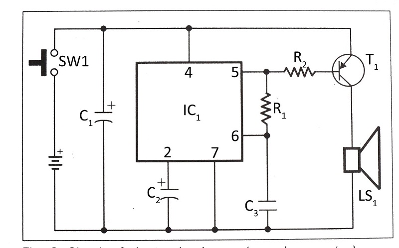
This document presents a verified circuit diagram for a simple, interesting, and cost-effective electronic clapper (sound generator) circuit, along with a description of its functionality. The electronic clapper circuit is designed to activate sound generation through the detection of sound...
This is a simple sawtooth generator circuit. The advantages of this circuit include low cost and the ability to produce an auxiliary square wave at the same frequency. This circuit can be utilized to sweep the frequency of another...
A useful feature of this circuit is that the frequency can be changed by modifying the capacitor value. A switch can be added to select between various frequencies. This circuit utilizes a capacitor in conjunction with an oscillator to determine...
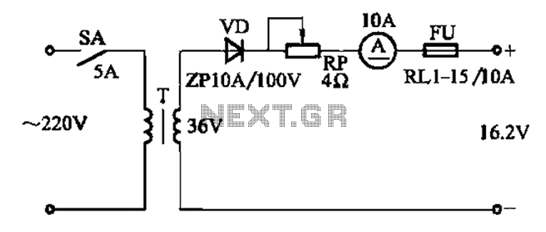
The adjustment potentiometer RP is utilized to modify the charging current. The adjustment potentiometer, designated as RP, serves a critical function in regulating the charging current within an electronic circuit. This component is typically a variable resistor that allows for...