
3v low battery voltage flasher

The circuit operates on a simple principle of voltage monitoring and low-power consumption, making it suitable for battery-operated devices. The use of a voltage detector IC ensures accurate monitoring of the battery voltage levels. When the voltage drops to the threshold of approximately 2.4 volts, the open-drain output of the IC transitions low, signaling the need for action.
The two-transistor oscillator circuit is configured to respond to this signal, generating a series of short pulses to drive the LED. The design of the oscillator allows it to operate efficiently, producing a flashing effect while consuming minimal current. The LED flashes for a duration of 2 ms, providing a clear visual indication of the battery status without drawing significant power from the battery itself.
This circuit can be particularly useful in applications where battery life is critical, such as in portable electronics or remote sensors. The careful selection of components and the low standby current ensure that the warning system does not interfere with the overall battery performance. Additionally, the simplicity of the design allows for easy implementation in various projects, making it accessible for hobbyists and engineers alike. Overall, this battery warning circuit serves as an effective solution for monitoring battery health in a compact and energy-efficient manner.The hobby circuit below can be connected to a 3v battery, to give you some warning when the battery is nearing its end of life. It will flash a LED when the battery voltage drops to about 2. 4 volts. The electronic circuit draws only 1ua of current in standby mode and jumps to only 20ua when flashing, so it can safely be included without depleting the battery energy.
A voltage detector IC from Panasonic (Microchip also makes similar devices) is used to monitor the battery voltage. The device`s open drain output swings low, when the battery voltage is below 2. 4 to 2. 5 volts. This action turns on the two transistor oscillator circuit, which drives the LED with short current pulses lasting only 2ms.
🔗 External reference
Related Circuits
This circuit uses three easily available 555 timer ICs. All three work as astable multivibrators. The first 555 has an on period and off period equal to 1 sec. This IC controls the on/ off periods of the other...

The aim of this project was to develop a linear analogue amplifier designed for laboratory use. This amplifier has to realise a voltage amplification of 10x and is intended to amplify function generator signals for tests. Power supply requirements:...

Often, for various reasons, individuals forget or are unable to water the plants in their homes. Many humidity sensor units merely alert users with a beeping sound or a flashing light when the pot requires watering. However, what if...

IC1-a, IC1-b, IC2-a, and IC2-b all operate with a gain of approximately 19. Their outputs are combined through level-control potentiometers, and the resulting signal is amplified by IC3-a before being sent to the tone-control stage IC3-b. Finally, the output...
The above pictured schematic diagram is just a standard constant current model with a added current limiter, consisting of Q1, R1, and R4. The moment too much current is flowing biases Q1 and drops the output voltage. The output...
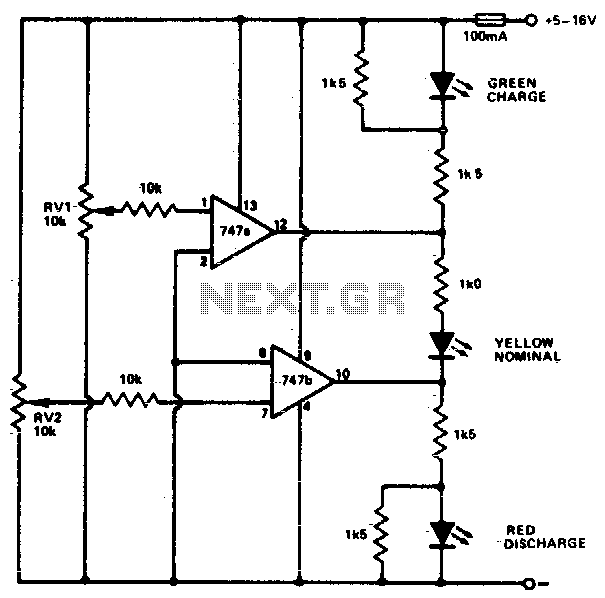
This circuit monitors car battery voltage and indicates nominal supply voltage, as well as low or high voltage conditions. RV1 and RV2 are used to adjust the thresholds at which the red/yellow and yellow/green LEDs activate or deactivate. For...