
Simple Lead Acid Battery Charger
The described circuit is a constant current source with an integrated current limiting feature, primarily designed for charging applications but versatile enough to function as a standard power supply. The core components include a transistor (Q1), resistors (R1, R2, R3, R4), and a potentiometer (P1).
In operation, the circuit regulates current flow to prevent excessive output, which is crucial for protecting batteries during charging. When the current exceeds a predetermined threshold, Q1 becomes biased, leading to a reduction in output voltage. The output voltage formula, given as \( V_{out} = 1.2 \times \frac{(P1 + R2 + R3)}{R3} \), indicates that the output is influenced by the values of the resistors and the potentiometer, allowing for fine-tuning of the voltage output.
For battery charging, specific resistance values are calculated based on the battery voltage requirements. For instance, a 6V battery necessitates a charge voltage of 7.35V, which is derived from three cells at 2.45V each. The combined resistance of R2 and P1 is approximately 585 ohms for this configuration. Conversely, for a 12V battery, the required resistance value increases to about 1290 ohms.
The circuit's efficiency is contingent upon maintaining an input voltage that is at least 3V higher than the output voltage. This ensures that the LM317 voltage regulator operates within its optimal range. The LM317 requires adequate thermal management, necessitating the use of a sufficiently large heatsink to dissipate heat generated during operation.
The transistor Q1, specified as a BC140, can be substituted with alternatives such as the NTE128 or ECG128, which are compatible and maintain similar operational characteristics. The inclusion of a trimmer potentiometer (P1) allows for adjustable output, providing flexibility based on the specific application needs.
Overall, this circuit can be effectively utilized not only as a battery charger but also as a general-purpose power supply, making it a valuable design for various electronic projects.The above pictured schematic diagram is just a standard constant current model with a added current limiter, consisting of Q1, R1, and R4. The moment too much current is flowing biases Q1 and drops the output voltage. The output voltage is: 1.2 x (P1+R2+R3)/R3 volt. Current limiting kicks in when the current is about 0.6/R1 amp. For a 6-volt battery which requires fast-charging, the charge voltage is 3 x 2.45 = 7.35 V. (3 cells at 2.45v per cell). So the total value for R2 + P1 is then about 585 ohm. For a 12 V battery the value for R2 + P1 is then about 1290 ohm. For this power supply to work efficiently, the input voltage has to be a minimum of 3V higher than the output voltage. P1 is a standard trimmer potentiometer of sufficient watt for your application. The LM317 must be cooled on a sufficient (large) coolrib. Q1 (BC140) can be replaced with a NTE128 or the older ECG128 (same company). Except as a charger, this circuit can also be used as a regular power supply. 🔗 External reference
Related Circuits
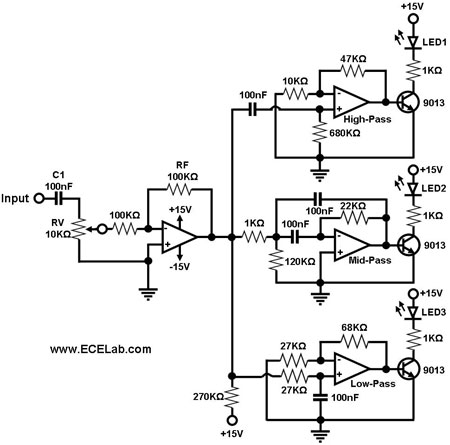
Figure 1 illustrates a simple circuit designed for converting an audio signal (such as one from the output terminals of a CD player). The circuit primarily consists of a buffer/amplifier stage and three filtering circuits: a high-pass filter, a...
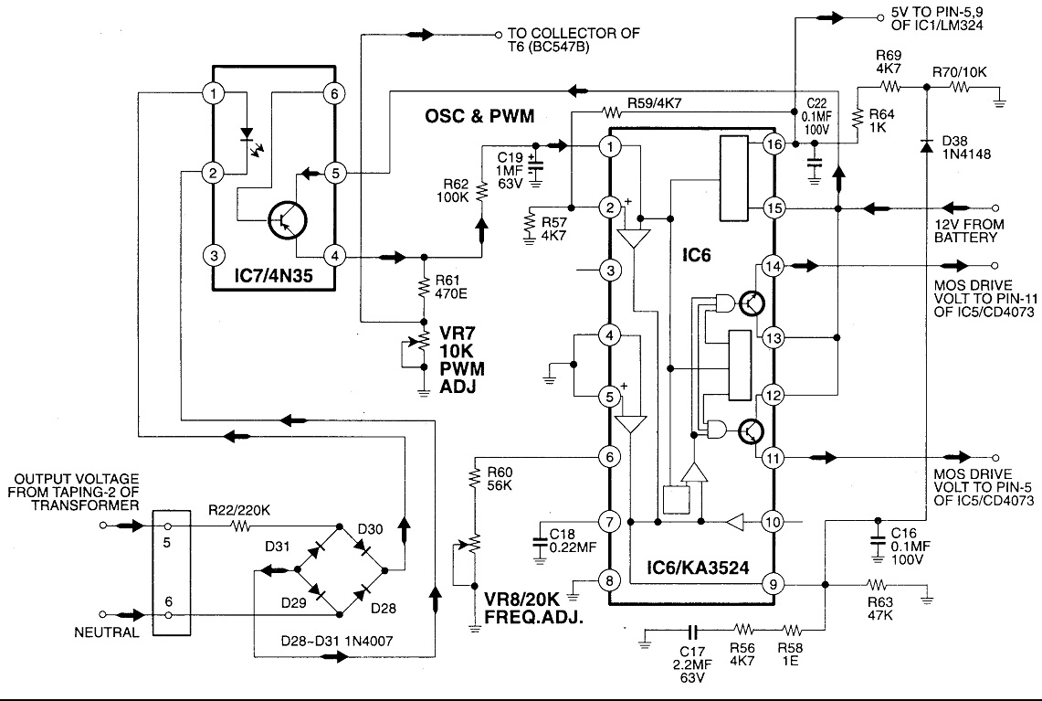
Circuit No. 1 (Oscillator Circuit and Feedback Circuit) Circuit No. 2 (MOS Driver Circuit) Final Product: - Operation of Circuit No. 1 (Oscillator Circuit and Feedback Circuit) This inverter utilizes Pulse Width Modulation (PWM) technology. The working principle of...
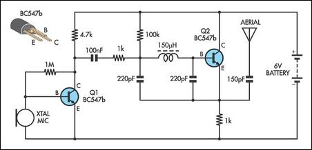
This AM transmitter is designed for simplicity and ease of construction. It utilizes a single-winding inductor that is not tapped, eliminating the need for custom winding. A readily available RF choke, such as the Jaycar Cat LF-1536, can be...
This circuit will charge a 12v battery (10 NiMH cells) @ approx 220mA. It is a very simple circuit but requires correct setting up. The circuit is designed around a 12vDC, 500mA plug pack. This type of plug pack...
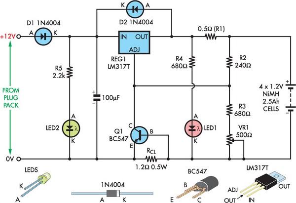
The LM317 is a well-established high-performance voltage regulator. Its output voltage remains stable despite variations in load, supply voltage, and temperature, making it an ideal component for a float charger designed for NiMH cells. Float charging effectively maintains the...
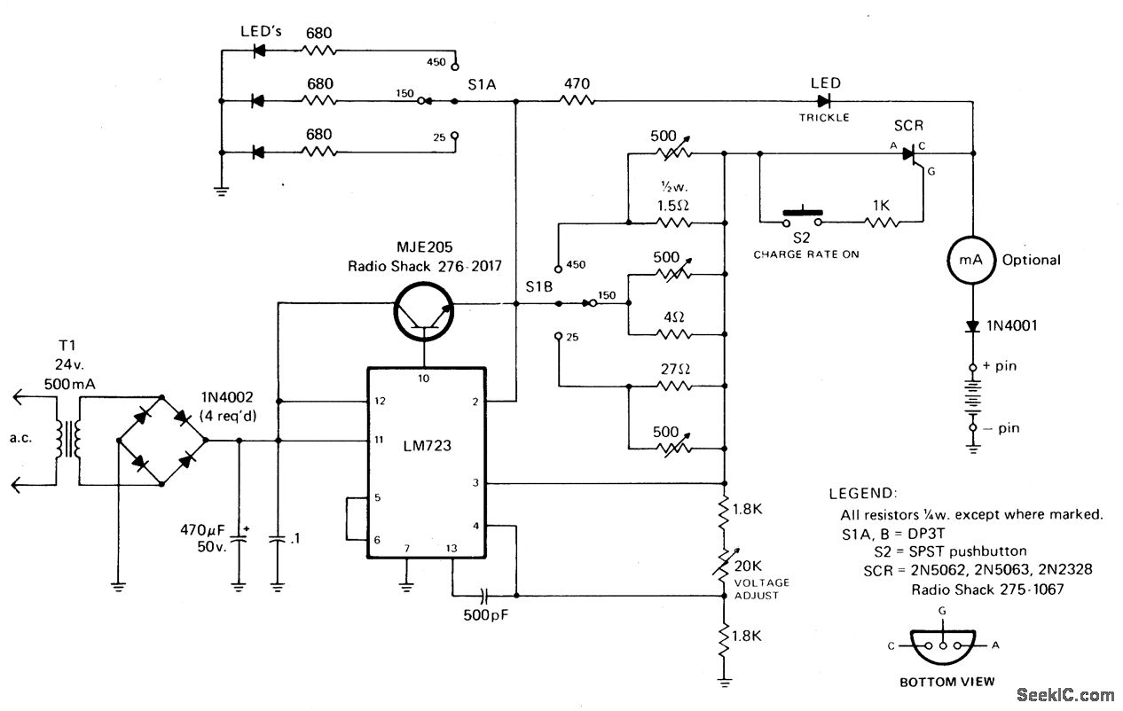
The rectified and filtered voltage from the 24 Vac transformer is applied to the LM723 voltage regulator, along with an NPN pass transistor configured for constant current supply. A 470-ohm resistor limits the trickle current until the momentary pushbutton...