
Linear Voltage multiplier circuit
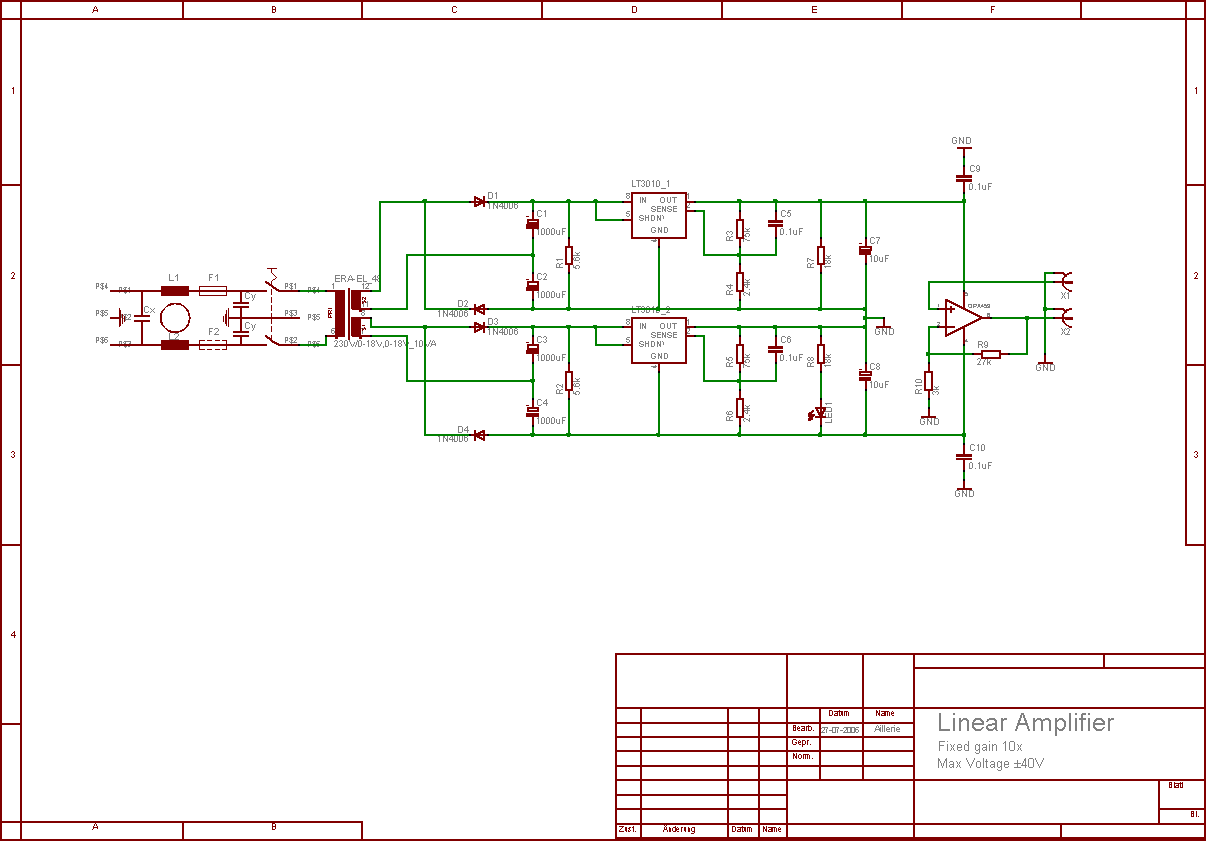
The linear analogue amplifier designed for laboratory applications utilizes an OPA453 operational amplifier, which is specifically chosen for its capability to handle high voltage ranges, up to ±40V. The amplifier configuration is set to achieve a fixed voltage gain of 10x, allowing it to amplify input signals with a maximum amplitude of ±4V. This results in an output signal that can reach ±40V, making it suitable for a variety of testing scenarios, particularly those involving function generators.
The power supply for the amplifier is derived from a standard 230VAC mains source, which is first transformed down to 18V/18V using a step-down transformer. This transformer is configured with a 1:1+1 winding ratio, effectively providing two separate 18V outputs. To increase the voltage further, two voltage doubler circuits are employed, which convert the 18V outputs into approximately 48V, ensuring that the operational amplifier receives sufficient voltage for its operation.
To regulate the output voltage and ensure stability, two LT3010 adjustable linear voltage regulators are integrated into the design. These regulators are critical for providing a smooth and stable ±40V supply to the OPA453, thus maintaining the performance and reliability of the amplifier during operation. The OPA453 itself boasts a bandwidth of 7.5MHz, making it capable of handling signals with frequency components up to 100kHz, which is essential for the intended application of amplifying square wave signals.
The amplifier's design has been validated through extensive testing, where it successfully operated under high output conditions without any signal degradation or variations. This robust performance underscores the effectiveness of the chosen components and the overall circuit design, making it a reliable tool for laboratory use.The aim of this project was to develop a linear analogue amplifier designed for laboratory use. This amplifier has to realise a voltage amplification of 10x and is intended to amplify function generator signals for tests. Power supply requirements: 230VAC 50 Hz. Fixed gain: 10x. Max. input amplitude: up to ±4V. Bandwidth: DC to 100kHz for square waves signals. High output load drive: 50mA continuous. During the tests, no problems have occurred. The amplifier ran several days with a high voltage output signal (±40V square wave with 20kHz) without any variation of the signal.
For the amplification an OPA453 high voltage operational amplifier is used, because a standard operational amplifier cannot be used in the voltage range of ±40V. This rail-to-rail OpAmp can operate with a power supply in the range of ±10V to ±40V. Thus the output amplitude can reach almost ±40V (which is acceptable). That is: 10x (fixed gain) ±4V (input amplitude). Furthermore the OPA453 has a 7.5MHz bandwidth and a high output load drive of 50mA continuous current.
To sum up, the OPA453 is the ideal component to fulfil all the constraints for our linear amplifier. A solution using the 230VAC mains supply was selected for this project. It is fed into a 230VAC to 18V/18V transformer (1:(1+1)) with two voltage doublers in order to obtain two 48V voltages. Then two LT3010 adjustable linear regulators are added in order to obtain a smooth ±40V supply voltage for our OPA453 OpAmp.
🔗 External reference
Related Circuits
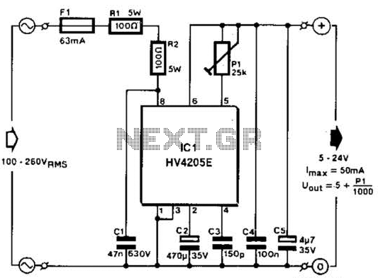
Direct derivation of 5 to 24 Vdc from AC mains without a transformer is possible with this circuit. Note that a direct mains connection to the DC output exists. Suitable safety precautions must be taken. This circuit design allows for...
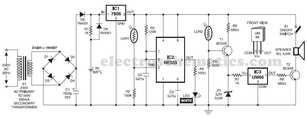
This musical light alarm circuit is very simple and uses only seven components, including a light-dependent resistor (LDR) and a 3.6V battery or three 1.2V rechargeable batteries. The well-known UM66 is utilized as the sound generator, providing a pleasant...
The receiver circuit in Figure 1 activates an audio alarm when the transmitter (Figure 2) moves beyond a specified perimeter. The transmitter functions as a voltage-controlled oscillator, operating at approximately 915 MHz within the unlicensed ISM (industrial/scientific/medical) band. It...
Once again my collection of projects creation has been interrupted by another necessity. Patrick and other people have asked me for a circuit of a VHF power amplifier. These circuits are my "standard" building blocks that can be used...
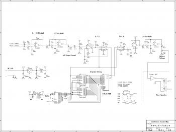
This is an easy-to-build surround sound processor circuit utilizing the digital delay processing method. This audio processor does not employ any specialized function integrated circuits that are difficult to obtain, and it is designed using only common-purpose integrated circuits....
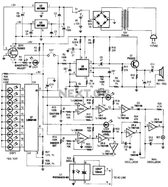
A gas sensor (TGS823 from Allegro Electronics, Cornwall Bridge, CT 06754) conducts in the presence of explosive gases. U5 is a voltage-to-frequency converter that produces a frequency proportional to the sensor conductance. The output frequency ranges from 100 Hz...
Warning: include(partials/cookie-banner.php): Failed to open stream: Permission denied in /var/www/html/nextgr/view-circuit.php on line 713
Warning: include(): Failed opening 'partials/cookie-banner.php' for inclusion (include_path='.:/usr/share/php') in /var/www/html/nextgr/view-circuit.php on line 713