
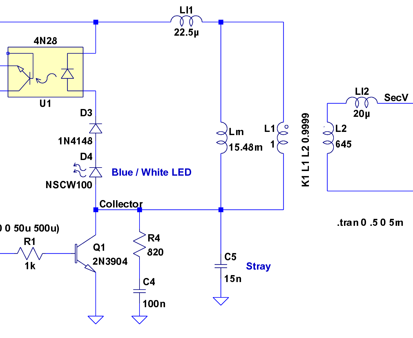
3V to 5V Converter Circuit
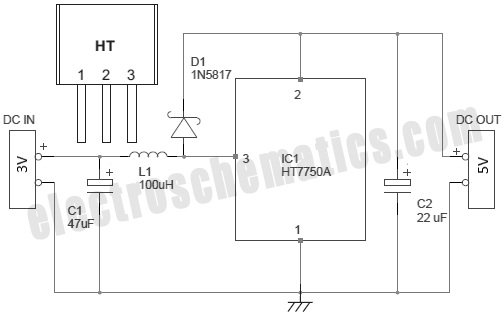
To convert AC voltage to DC voltage effectively, a typical approach involves the use of a transformer, rectifier, and filter circuit. The transformer steps down the high voltage AC from the wall outlet to a lower AC voltage suitable for the microcontroller's requirements. The rectifier, which can be a diode bridge configuration, converts the AC voltage into pulsating DC. The filter, often a capacitor, smooths out the pulsating DC to provide a more stable voltage level.
In more advanced designs, additional components such as voltage regulators may be included to ensure that the output DC voltage remains constant despite variations in input voltage or load conditions. This is crucial for microcontroller operation, as they require a stable voltage to function correctly.
Furthermore, safety features such as fuses or circuit breakers may be incorporated to protect the circuit from overcurrent conditions. Additionally, proper isolation techniques should be employed to prevent any high voltage from reaching the low voltage side of the circuit, ensuring user safety and equipment reliability.
Overall, the design of an AC to DC converter for microcontroller applications must take into account efficiency, size, heat dissipation, and safety to meet the specific requirements of the intended application.There are several ways to convert an AC voltage at a wall receptacle into the DC voltage required by a microcontroller. Traditionally, this has been done w.. 🔗 External reference
Related Circuits
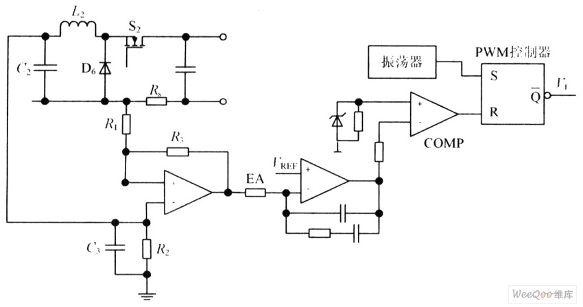
The circuit is capable of enhancing the system power factor to a value exceeding 0.99. It effectively reduces the waveform distortion of the input supply current, ensuring compliance with GB15144 standards, with a distortion index lower than level L....
To extend the measurement range of an available ADC (analog to digital converter), autoranging can be utilized. If implemented on multiplexed input, this... Autoranging is a technique employed in electronic measurement systems to automatically adjust the range of an analog-to-digital...
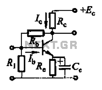
Basic reference transistor bias circuit - Mixed Negative feedback The basic reference transistor bias circuit utilizing mixed negative feedback is a fundamental electronic configuration designed to stabilize the operating point of a transistor. This circuit typically employs a combination of...
The yellow wires on the far right serve as temporary power connections, allowing battery power to enter through the contact studs located in the large holes that press against the radio's battery terminals. The cable in the lower right...
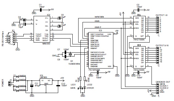
This basic PIC-based RS-232 serial interface can control up to 120 digital TTL outputs. The described circuit utilizes a PIC microcontroller to facilitate communication via the RS-232 protocol, which is a standard for serial communication. The interface primarily serves to...
A simple preamplifier circuit is often required, utilizing a few components for ease of construction. This circuit employs an operational amplifier, specifically the Motorola TCA5550, which features a dual amplifier configuration. It provides outputs for adjusting volume, balance, treble,...