
4 Channel Digital Logic Analyzer
The circuit design for a PC parallel port-based DLA (Data Line Adapter) focuses on safeguarding the parallel port connections on the motherboard. The parallel port, commonly used for connecting printers and other peripherals, is susceptible to damage from overvoltage or short circuits.
The protection circuit typically includes several key components: resistors, diodes, and capacitors. Resistors are used to limit the current flowing into the port, thereby preventing excessive current from damaging the internal circuitry. Diodes are implemented in a reverse-bias configuration to shunt any overvoltage conditions away from the port, effectively clamping the voltage to a safe level. Capacitors may be included for filtering out noise, ensuring that the signals transmitted through the port remain stable and free from interference.
The overall design should ensure that the protection circuit does not interfere with normal operation. The components must be selected based on the specifications of the parallel port, taking into account the maximum current and voltage ratings. Additionally, the layout of the circuit is crucial; it should minimize parasitic inductance and capacitance to maintain signal integrity.
In conclusion, this protection circuit is an essential addition to any design involving a PC parallel port, enhancing reliability and extending the lifespan of both the port and connected devices.This is one of the simplest circuit for a PC parallel port based DLA. The Circuit is mainly used to protect the port which is fabricated on the motherboard itself 🔗 External reference
Related Circuits
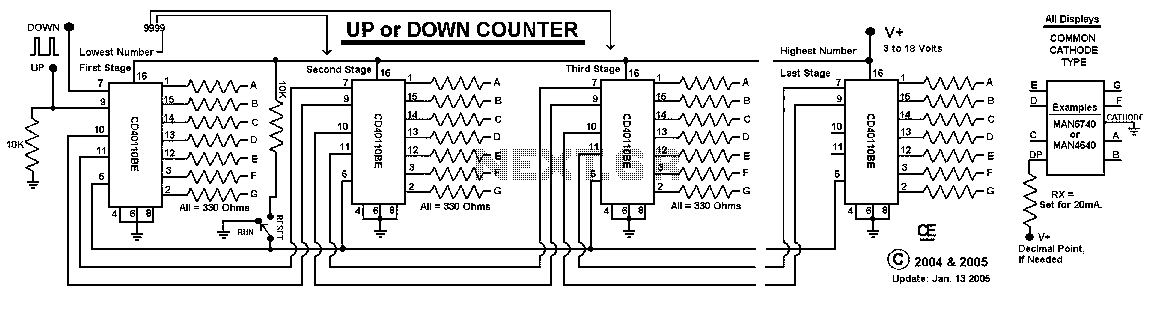
This Circuit uses a CD40110BE, Up/Down Counter IC's. This IC is able to Source Each Segment with 25 mA, Giving a Very Nice Bright Display. The 7 Segment Displays MUST be a Common Cathode Type, as I have used...
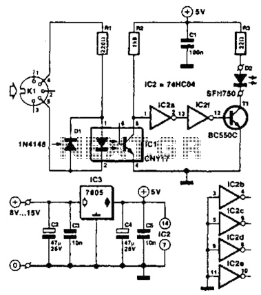
Used for digital control of musical instruments, this transmitter converts digital data signals into equivalent optical signals for a fiber optic cable interface. Optocoupler IC1 provides isolation, driving IC2-a and -b, and T1, ultimately providing a cable driver LED...
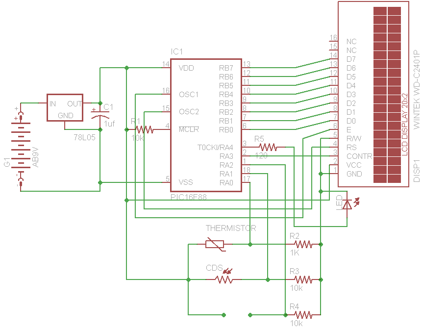
The initial concept for this project involves interfacing the WINTEK WD-C2401P LCD panel with a PIC microcontroller. The intention is to incorporate several ADC readings to provide useful information on the LCD. PORTB on the PIC serves as the...
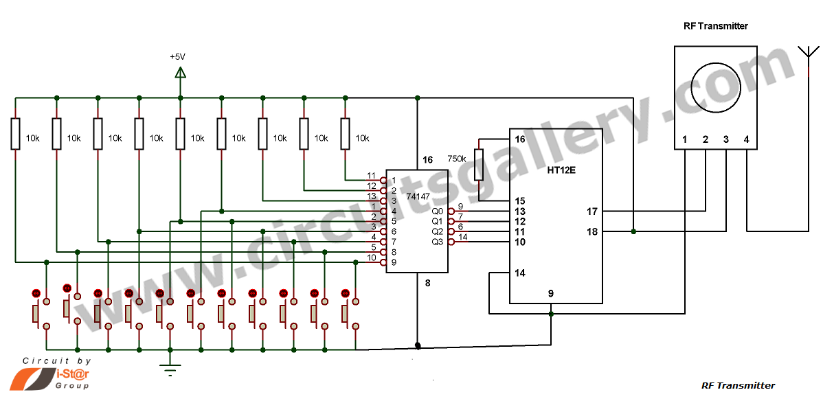
This is a hobby circuit for a multi-channel remote control system that allows the control of eight different appliances. The primary components of this multi-channel remote control circuit are the RF receiver and transmitter. By utilizing this circuit, it...
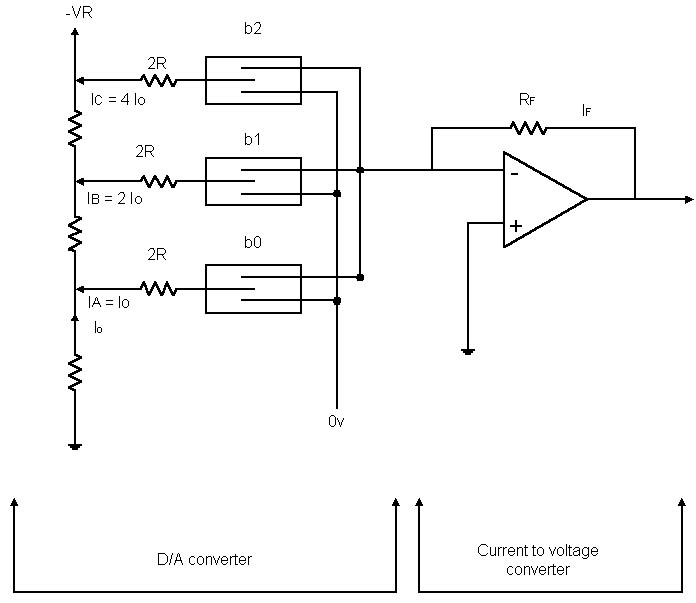
Before examining the various analog-to-digital (A-D) and digital-to-analog (D-A) conversion processes, it is useful to review the properties of each type of representation; in particular, this may help select the representation most suited to the problem at hand. An...
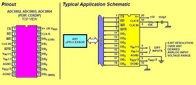
The circuit involves 8-bit, microprocessor-compatible analog-to-digital converters (A/D converters). It utilizes the ADC0804 chip for converting analog signals to digital form, in conjunction with an AT89C2051 microcontroller. The ADC0802 family consists of CMOS 8-bit, successive-approximation A/D converters that employ...