
4 in 1 burglar alarm pcb

This alarm circuit employs a combination of light-dependent resistors (LDRs), door switches, and a touch-sensitive point to create a comprehensive security system. The circuit utilizes an integrated circuit (IC1) to process the signals from the various sensors. The LDRs serve as the primary detection mechanism, responding to changes in light levels to identify potential intruders.
The configuration of LDR1 and LDR2 allows for versatile placement in different environments. LDR1, positioned in darkness, is sensitive to light changes caused by intruders, while LDR2 monitors for shadows in well-lit corridors. The adjustable sensitivity via potentiometers VR1 and VR2 ensures that the system can be tailored to specific lighting conditions and the environment's unique characteristics.
The inclusion of a wire or door switches provides additional security measures. The wire acts as a trip mechanism that will activate the alarm if broken, while the door switches confirm the status of the door's position. The touch-sensitive point enhances the security by allowing the system to detect physical contact, providing a multi-faceted approach to intrusion detection.
The relay (RL1) functions as a switch to activate the alarm system, which can be configured to suit various voltage and current requirements, ensuring compatibility with different alarm types. The circuit's design also emphasizes the importance of battery backup to maintain functionality during power outages, further enhancing reliability.
In summary, this circuit design presents an effective and adaptable burglar alarm system that integrates multiple detection methods to ensure comprehensive security coverage, with adjustable parameters for sensitivity and operation tailored to specific user needs. Proper installation and calibration of the components are crucial for optimal performance and to minimize false alarms.I n this circuit, the alarm will be switched on under the following four different conditions: 1. When light falls on LDR1 (at the entry to the premises). 2. When light falling on LDR2 is obstructed. 3. When door switches are opened or a wire is broken. 4. When a handle is touched. The light dependent resistor LDR1 should be placed in darkness nea r the door lock or handle etc. If an intruder flashes his torch, its light will fall on LDR1, reducing the voltage drop across it and so also the voltage applied to trigger 1 (pin 6) of IC1. Thus transistor T2 will get forward biased and relay RL1 energise and operate the alarm. Sensitivity of LDR1 can be adjusted by varying preset VR1. LDR2 may be placed on one side of a corridor such that the beam of light from a light source always falls on it.
When an intruder passes through the corridor, his shadow falls on LDR2. As a result voltage drop across LDR2 increases and pin 8 of IC1 goes low while output pin 9 of IC1 goes high. Transistor T2 gets switched on and the relay operates to set the alarm. The sensitivity of LDR2 can be adjusted by varying potentiometer VR2. A long but very thin wire may be connected between the points A and B or C and D across a window or a door.
This long wire may even be used to lock or tie something. If anyone cuts or breaks this wire, the alarm will be switched on as pin 8 or 6 will go low. In place of the wire between points A and B or C and D door switches can be connected. These switches should be fixed on the door in such a way that when the door is closed the switch gets closed and when the door is open the switch remains open. If the switches or wire, are not used between these points, the points should be shorted. With the help of a wire, connect the touch point (P) with the handle of a door or some other suitable object made of conducting material.
When one touches this handle or the other connected object, pin 6 of IC1 goes ½low ½. So the alarm and the relay gets switched on. Remember that the object connected to this touch point should be well insulated from ground. For good touch action, potentiometer VR3 should be properly adjusted. If potentiometer VR3 tapping is held more towards ground, the alarm will get switched on even without touching. In such a situation, the tapping should be raised. But the tapping point should not be raised too much as the touch action would then vanish. When you vary potentiometer VR1, re-adjust the sensitivity of the touch point with the help of potentiometer VR3 properly.
If the alarm has a voltage rating of other than 6V (more than 6V), or if it draws a high current (more than 150 mA), connect it through the relay points as shown by the dotted lines. As a burglar alarm, battery backup is necessary for this circuit. Note: Electric sparking in the vicinity of this circuit may cause false triggering of the circuit. To avoid this adjust potentiometer VR3 properly. 🔗 External reference
Related Circuits
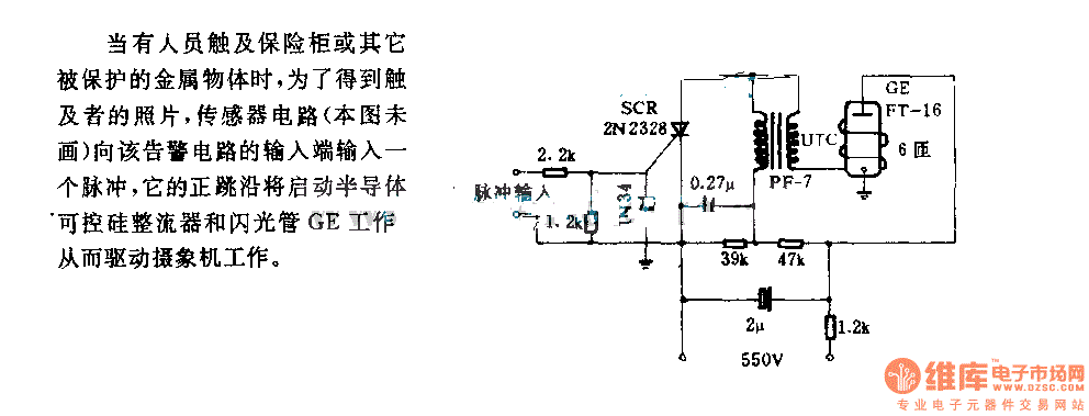
When an individual touches the safety box or other protected metal objects, the sensor circuit generates a pulse to the alarm circuit. The positive edge of this pulse activates the semiconductor and thyristor flash GE, subsequently triggering the camera...

Posts from PCB Schematic Design with DxDesigner tagged DxDesigner. The information pertains to the use of DxDesigner, a tool utilized for PCB schematic design. DxDesigner is part of the broader suite of design tools that facilitate the creation, editing, and...

The source code features a FAT12 filesystem that can be utilized to create custom flash drives for various projects. This source code is based on the Microchip Applications libraries for the Device Mass Storage SD Card data logger using...

This document presents a simple schematic of a multitone siren alarm circuit. The multitone siren is effective for reverse horns, burglar alarms, and various other applications. It generates five distinct audio tones, making it significantly more attention-grabbing than a...
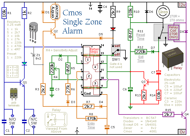
This circuit includes automatic exit and entry delays, a timed bell cut-off, and a system reset feature. It is designed to support both normally-open and normally-closed switches and can accommodate standard input devices such as pressure mats, magnetic reed...

This circuit automates the control of street or porch lights. The automatic lamp controller circuit utilizes a 7806 voltage regulator IC, which can be employed to automate street lights, tube lights, or any other home electrical lighting systems. The...
Warning: include(partials/cookie-banner.php): Failed to open stream: Permission denied in /var/www/html/nextgr/view-circuit.php on line 713
Warning: include(): Failed opening 'partials/cookie-banner.php' for inclusion (include_path='.:/usr/share/php') in /var/www/html/nextgr/view-circuit.php on line 713