
temperature logger part 6 schematics pcb and source code

The described system integrates a FAT12 filesystem to facilitate the management of data storage on custom flash drives, specifically tailored for projects requiring data logging capabilities. The use of Microchip Applications libraries allows for compatibility with the Device Mass Storage SD Card data logger, enhancing the versatility of the solution.
The USB temperature logger functionality is central to the design, enabling real-time temperature monitoring and data logging. The source code serves as a foundation that can be expanded upon, allowing developers to introduce additional features or optimize existing functionalities.
One critical aspect that requires attention is the robustness of the logger, particularly regarding power management. Implementing a power failure detection mechanism would significantly enhance the reliability of the logger, ensuring that data integrity is maintained even in the event of unexpected battery depletion. This could involve the use of capacitors to provide a buffer during power loss or implementing a software routine that safely shuts down the logger upon detecting low battery conditions.
Furthermore, the PCB design includes provisions for monitoring battery voltage, which is a vital feature for maintaining operational reliability. The firmware must be updated to utilize this capability, allowing for real-time voltage readings that can trigger alerts or safe shutdown procedures when voltage drops below a critical threshold.
In summary, the integration of a FAT12 filesystem, USB temperature logging capabilities, and robust power management features positions this project as a comprehensive solution for data logging applications. Future enhancements to the source code and firmware will further solidify its reliability and functionality in various operational environments.The source code contains a FAT12 filesystem that can be reused to make custom flash drives for other projects. The source code (based on Microchip Applications libraries -Device Mass Storage SD Card data logger- MPLABX): Simple USB temperature logger source code The source code could be improved to increase the robustness of the logger (especially in the case of battery power failure
while on logging mode). The PCB allows the monitoring of the battery voltage, it just needs to be implemented in the firmware. 🔗 External reference
Related Circuits
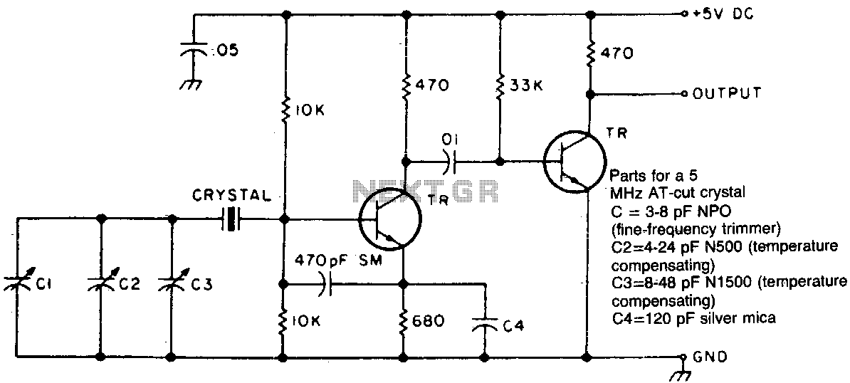
Two different negative-coefficient capacitors are blended to produce the desired change in capacitance to counteract or compensate for the decrease in frequency of the "normal" AT-cut characteristics. The circuit utilizes a combination of two negative-coefficient capacitors to achieve a specific...
This project displays telephone numbers decoded from tones. A microphone picks up the tones, a preamplifier boosts the signals, an SSI-202 DTMF chip decodes the tones, a Basic Stamp acts as an interface to an LCD display and also...

The circuit consists of a grounded source and an emitter follower configuration. The source is grounded, and the emitter is combined with a common-collector transistor amplifier. As shown in the figure, VTI is a vibration-grounded field-effect transistor amplifier, while...
This circuit is designed for low-power transmitters that operate with a positive keying voltage. The transistors Q1, Q2, and Q3 are configured as a switching amplifier. When the key is pressed, the collector of Q3 connects to ground, which...
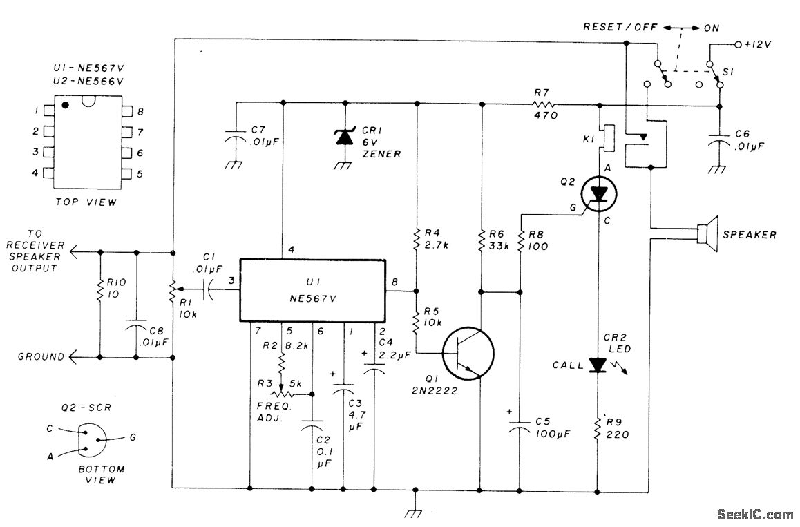
This circuit allows for monitoring a local VHF FM repeater for calls from friends without the need to listen to the background chatter or noise from the repeater. Its operation mimics that of Motorola paging units, where a special...
This simple stereo encoder circuit schematic is built with two ICs, MMC4066E and MMC4047, along with one transistor, BC547B. The audio output is taken from pins 2 and 3 of IC1. The stereo encoder circuit utilizes the MMC4066E, which is...