
Multitone Siren Alarm

The multitone siren alarm circuit utilizes a combination of oscillators and a sound-generating device, typically a piezoelectric speaker or a small loudspeaker, to produce multiple tones. The circuit may include a microcontroller or a dedicated tone generator IC, which is programmed or configured to cycle through the five different frequencies. These frequencies are carefully chosen to ensure that they are distinct enough to be easily recognized by the human ear.
The circuit design typically features a power supply section, providing the necessary voltage and current to operate the components. A resistor-capacitor (RC) network may be employed to shape the oscillation frequencies, while a transistor or MOSFET may be used to drive the speaker, allowing for sufficient output power without distortion.
In applications such as burglar alarms, the multitone siren can be programmed to activate under specific conditions, enhancing the alertness of nearby individuals. The use of multiple tones can also be beneficial in environments where a single tone may blend into the background noise, making the alarm less effective.
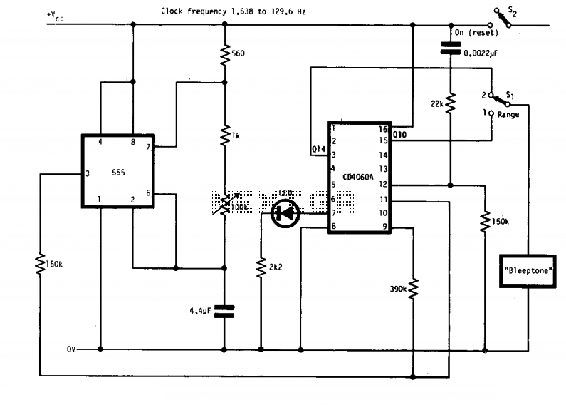
Overall, the multitone siren alarm circuit is a versatile solution for various signaling applications, providing an effective means of alerting individuals to potential threats or emergencies through its distinctive audio output.Here the simple schematic of multitone siren alarm circuit. This multitone siren is effective for reverse horns, burlgar alarms, and many others. It generates five various audio tones and is much more earcatching than a single-tone siren. T.. 🔗 External reference
Related Circuits

This alarm siren circuit produces a continuous frequency sweep, resulting in a warbling sound. The duration of the warbling is approximately 6 seconds, with 3 seconds allocated for frequency sweeping upward and 3 seconds for sweeping downward. The alarm siren...

An ultra-simple circuit of the tilt sensor alarm can be fabricated using readily available, inexpensive components. The circuit operates as a true transistor-based design. The tilt sensor alarm circuit utilizes a tilt sensor, which is a device that detects the...
Simple Burglar Alarm / Door Alarm Circuit Diagram. This project can be utilized to secure a door or window. It emits a loud beep and activates the room light when an intruder attempts to break the door lock. The Simple...
The circuit features two timing ranges: from 10 seconds to 5 minutes and from 1 minute to 80 minutes. It is powered by a 9-V battery. An LED is connected in a manner that allows for a consistent flashing...

This circuit utilizes a 555 timer integrated circuit (IC) as an alarm system designed to deter theft of luggage and prevent unauthorized entry into homes. The alarm is activated when a thin wire, typically as fine as a human...

The function of this circuit is to detect a sudden shadow falling on the light sensor and to activate a buzzer when this occurs. The light sensor is designed to monitor ambient light levels. The circuit utilizes a light-dependent resistor...