
4 Watts FM Transmitter
The FM transmitter circuit is designed to provide reliable transmission of frequency-modulated signals within the VHF band, specifically between 88MHz and 108MHz, which is the standard FM radio band. The circuit typically includes several key components such as a voltage regulator, oscillator, modulator, amplifier, and antenna.
The voltage supply of 12V to 16V is essential for the operation of the circuit, ensuring that all components receive adequate power for optimal performance. The current consumption of 100mA to 400mA indicates that the circuit is efficient, allowing for prolonged use without excessive power draw.
The oscillator is responsible for generating the carrier frequency, which is modulated by the audio signal to create the FM signal. This modulation process typically involves a varactor diode or a similar component that varies the capacitance in response to the audio input, thus changing the frequency of the oscillator slightly to encode the audio information onto the carrier wave.
The amplifier stage boosts the power of the modulated signal, allowing it to achieve the desired output of up to 4W. This output power is sufficient for local broadcasting, ensuring that the signal can be received clearly by standard FM receivers within a reasonable range.
Finally, the antenna plays a critical role in radiating the FM signal into the environment. The design of the antenna should be matched to the operating frequency to maximize efficiency and range.
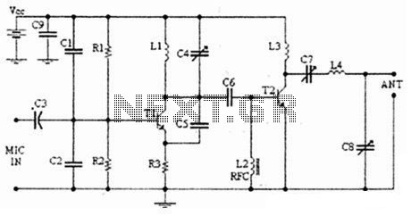
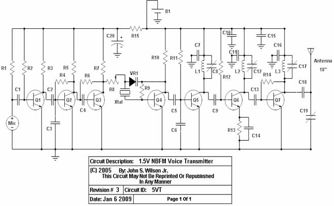
Overall, this FM transmitter circuit is a valuable tool for various applications, including hobbyist projects, educational demonstrations, and small-scale broadcasting. Proper assembly and tuning of the components will ensure effective operation and compliance with relevant transmission regulations.The following diagram is the FM transmitter circuit with FM transmision up to 4W. Voltage supply for this circuit is 12-16V with current consumption of 100-400mA. This circuit works with frequency of emission range of 88-108MHz. Components.. 🔗 External reference
Related Circuits
The modulator and oscillator comprise two NPN transistors. The base of the modulator transistor is powered by a bidirectional current source, with the voltage range for the high condition restricted by a saturating PNP collector connected to the pin...
The transmitter described here includes an additional RF power amplifier stage following the oscillator stage, which increases the output power to 200-250 milliwatts. When connected to a properly matched 50-ohm ground plane antenna or a multi-element Yagi antenna, this...

The LV2283VB is an FM Transmitter Integrated Circuit (IC). The multiplex (MPX) block generates a stereo modulated composite signal from left and right audio inputs. The RF Voltage-Controlled Oscillator (VCO) incorporates the FM modulation function. The Phase-Locked Loop (PLL)...
This transmitter emits an FM signal within the 88 to 108 MHz frequency range, featuring a tone of 19 kHz. This tone can activate the FM MPX pilot carrier indicator, allowing interfacing with external devices. L4 is designed for...
Nice small audio amplifier which use only few parts to give good quality sound. This amp can be used as a simple booster, the heart of a more complicated amplifier or used as a guitar amp. Although not perfect,...
Construct this circuit utilizing a Digi-Key Electronics Barrel Crystal (CA-301) with a frequency of 15 MHz to achieve a standard output frequency of 150.00 MHz. For frequency customization, follow the provided instructions. Typically, this circuit is designed to operate...
Warning: include(partials/cookie-banner.php): Failed to open stream: Permission denied in /var/www/html/nextgr/view-circuit.php on line 713
Warning: include(): Failed opening 'partials/cookie-banner.php' for inclusion (include_path='.:/usr/share/php') in /var/www/html/nextgr/view-circuit.php on line 713