
Remote-Control Transmitter Circuit
The described FM transmitter circuit operates within the standard FM broadcast band, specifically designed to transmit signals that can be received by standard FM radios. The 19 kHz tone is significant as it serves as a pilot tone for multiplexing, which is essential for stereo FM broadcasting. This pilot tone enables the receiver to recognize the presence of a stereo signal, thus activating the stereo decoder circuitry in compatible receivers.
The antenna (L4) is optimized for the 15 cm length, which is crucial for efficient transmission at the specified frequency range. The choice of wire gauge, #26, provides a balance between flexibility and resistance, ensuring that the inductors maintain their intended inductance values without excessive losses.
Inductor L1 is constructed with 9 turns of enameled wire, which helps form a resonant circuit in conjunction with the carbon resistor. The 54-ohm resistor is selected to match the impedance of the circuit, optimizing power transfer and minimizing reflections. L2, being only 2 turns wound over L1, serves as a coupling inductor that enhances the signal transfer between stages of the circuit.
Inductor L3, with 7 turns of #26 enameled wire on a 10-kΩ, ¼-W resistor, plays a role in filtering or further modifying the signal characteristics. The choice of a carbon resistor for L1 and L3 indicates a preference for stability and reliability in the circuit's performance.
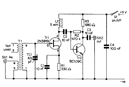
Overall, this circuit design highlights the importance of careful component selection and configuration in achieving a functional FM transmitter capable of interfacing with external devices and providing high-quality signal transmission within the FM band. This transmitter sends an FM signal in the 88-to 108-MHz range, with a tone of 19 kHz. This can be used to activate the FM MPX pilot carrier indicator, which can be interfaced to external devices. L4 is for use with a 15 CM wire antenna. LI is 9 turns of #26 enamelled wire on a 54-W 10-kQ resistor (carbon type), L2 is 2 turns wound over LI.
L3 is 7 turns of #26 enamelled wire on a 10-ka /4-W resistor. 🔗 External reference
Related Circuits
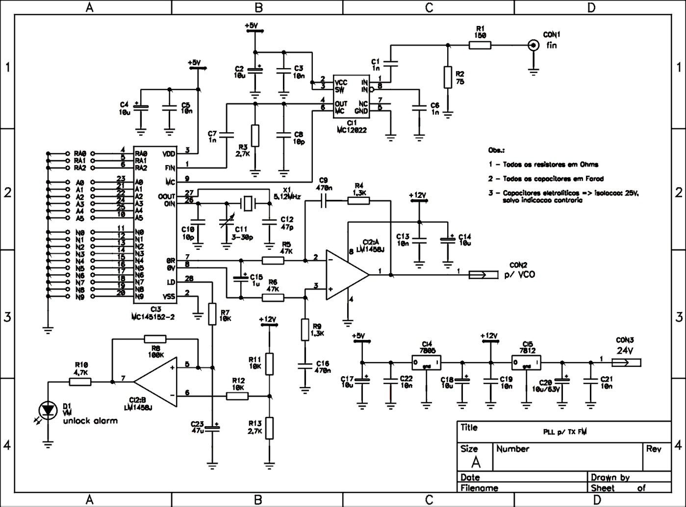
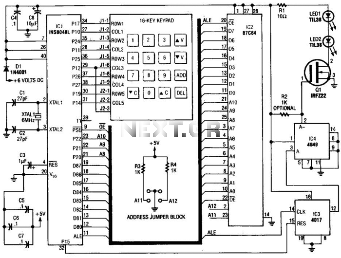
This is a schematic of a synthesized Phase-Locked Loop (PLL) for a low-power FM transmitter. It can also be utilized with other circuits, provided that the loop filter response, components, VCO tank circuit, and appropriate thumbswitch programming keys and...
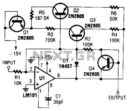
This operational amplifier circuit utilizes resistor and transistor feedback elements to function as a nonlinear amplifier. The resistors R4 and R6 can be adjusted to modify the breakpoints as needed. This operational amplifier circuit is designed to operate within the...
Sensitive FM Transmitter. Additional Notes: The default for the capacitors type is ceramic, preferably the NPO 1% type or equivalent. However, nothing critical is here; any type can be used. The sensitive FM transmitter circuit is designed to operate in...
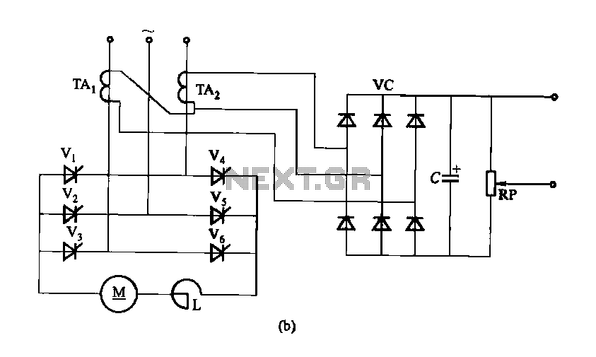
Figure 16-40 illustrates a three-phase rectifier circuit featuring a current cutoff feedback mechanism. In part (a) of the figure, three current transformers are utilized, while part (b) shows the configuration using two current transformers connected in an open delta...
This simple aerial booster circuit design could serve as an alternative or a hobby project for creating an aerial booster device for Citizen Band (CB) radio. The aerial booster circuit is designed to enhance the performance of Citizen Band (CB)...

The hobby circuit described utilizes a unique approach to generate approximately 12,000 volts with a current of about 5 µA. It employs two silicon-controlled rectifiers (SCRs) that form dual pulse generator circuits. These SCRs discharge a 0.047 µF capacitor...