
40 segment led s meter
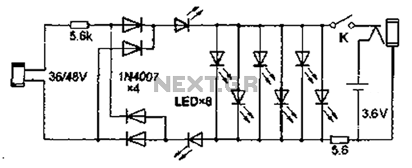
The circuit described involves a radio signal processing system that utilizes a series of LEDs to provide visual feedback based on the signal strength detected by the S-meter. The HIGH LEVEL potentiometer is critical for setting the maximum threshold at which all LEDs are illuminated, indicating optimal signal reception. Conversely, the LOW LEVEL potentiometer serves to define the minimum threshold, ensuring that no LEDs are lit when the signal falls below a certain level.
The use of a 10K resistor in place of the HIGH LEVEL potentiometer is advisable when the S-meter voltage exceeds 5 volts, as this adjustment helps to protect the circuit from potential damage due to excessive current. The integration of a 6.1-volt zener diode, connected in a specific manner, ensures that the voltage levels remain stable and within safe operating parameters. The 1K resistor pulling the zener diode up to 13 volts plays a crucial role in maintaining the voltage supply, while grounding the anode provides a reference point for the circuit.
The circuit's design allows for flexibility in current management through the use of adjustable resistors and potentiometers. The specified values for R1, R2, R3, and R4 indicate the relationship between the resistance and the desired LED current, allowing for precise control over the brightness and responsiveness of each LED segment. This adaptability is essential for tailoring the circuit to specific operational requirements and ensuring optimal performance in various signal conditions.Provide your radio with a actual cord signal, again acclimatize the HIGH LEVEL pot to the beginning of anecdotic the aftermost LED (all LEDs on). Remove the arresting completely, again acclimatize the LOW LEVEL pot to the beginning of no LEDs illuminated.
If your radios S-meter achievement is greater than 5 volts, you mau ambition to alter the HIG H LEVEL pot with a 10K resistor, and accommodate pin 6 of the right-most 3914 with the cathode of a 6. 1 volt zener diode, pulled up to 13 volts with a 1K resistor. The anode should be affiliated to ground. You may use a college voltage zener if necessary. This agreement provides 10ma per LED segment. Change the ethics to the resistors and pots to change the drive accepted to the LEDs. R1=12. 5/I R2=25/I R3=37. 5/I R4=50/I area I = the adapted LED current 🔗 External reference
Related Circuits
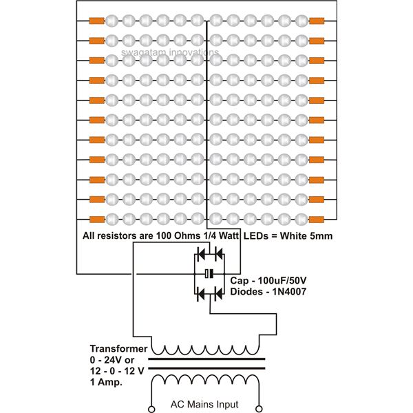
The use of white LEDs for home illumination is gaining popularity due to their high power efficiency. The diagram illustrates a simple circuit configuration that consists of multiple LEDs arranged in both series and parallel. In the LED tube...
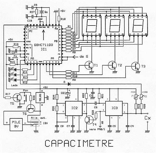
The proposed capacitance is a very powerful assembly to measure in 7 ranges capacitors of 1 pF to 999 uF, with an excellent precision of about 10^-3. The range change is fully automatic. The display shows 3 digits with...
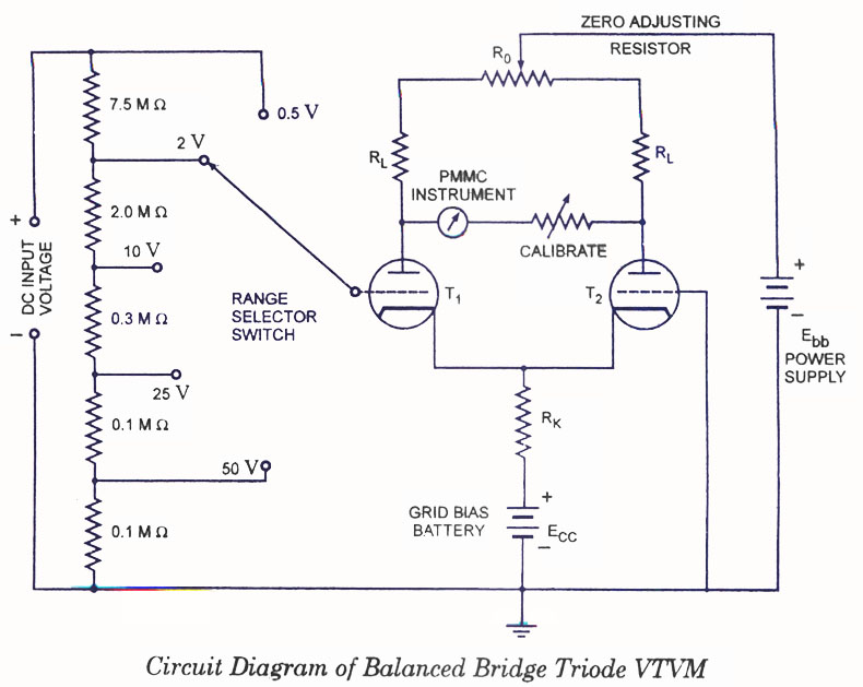
Voltmeters can be utilized for measuring both direct current (DC) and alternating current (AC) voltages and are widely used. These voltmeters are available in two types: vacuum tube and transistorized. In the vacuum tube version, two identical triodes, T1...
Also known as the Free lamp (commonly referred to as the Myanmar lamp by online sellers), this device operates using the voltage from a standard household fixed telephone line, eliminating the need for batteries or AC power. The lamp...
In conventional white LED design, the Max1916 low-dropout bias supply for white LEDs serves as a high-performance alternative to simple ballast resistors. The Max1916 is an integrated circuit designed to provide a stable and efficient bias supply for white LEDs....
A simple SWR meter first needs a calibration to Uv = 100 % (forward power). When switching over to Ur (reflected power) the SWR is indicated. This procedure has to be repeated every time a change is made to...
Warning: include(partials/cookie-banner.php): Failed to open stream: Permission denied in /var/www/html/nextgr/view-circuit.php on line 713
Warning: include(): Failed opening 'partials/cookie-banner.php' for inclusion (include_path='.:/usr/share/php') in /var/www/html/nextgr/view-circuit.php on line 713