
400V-60W push-pull DC-DC converter
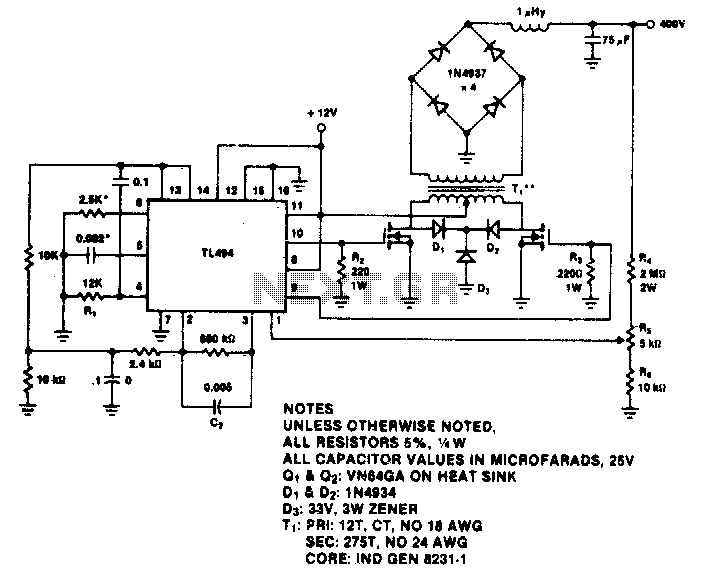
The TL494 is a versatile integrated circuit commonly used in switching power supply applications due to its ability to provide precise voltage regulation and efficient power conversion. This device operates at a nominal switching frequency of around 100 kHz, which is suitable for many applications requiring moderate power levels.
In terms of functionality, the TL494 features two error amplifiers that compare the feedback voltage from the output to a reference voltage, allowing for precise regulation of the output voltage. The output voltage can be adjusted using external resistors, enabling the design of power supplies that meet specific voltage requirements.
The output regulation capability of the TL494 is typically within 15% across the load range, from no-load conditions to a maximum output of 60 watts. This characteristic is crucial for applications where load variations are expected, ensuring that the output voltage remains stable and within acceptable limits even as the load changes.
In addition, the TL494 includes features such as a dead-time control to prevent cross-conduction in push-pull configurations, as well as a built-in oscillator for frequency stability. These features contribute to the overall efficiency and performance of the switching regulator circuit, making the TL494 an excellent choice for designers seeking reliable voltage regulation in their power supply designs.
Overall, the TL494 switching regulator is a robust solution for applications requiring efficient power management, with the capability to maintain output voltage stability across a wide range of operating conditions.The TL494 switching regulator governs the operating frequency and regulates output voltage. Switching frequency approximately 100 kHz for the values shown Output regulation is typically 15% from no-load to full 60 W. 🔗 External reference
Related Circuits
The TDA8444 is a digital-to-analog (D/A) converter integrated circuit (IC) produced by Philips. It is designed to convert digital signals into analog signals. The TDA8444 IC utilizes a 16-pin dual in-line package, with specific pin functions and data outlined...
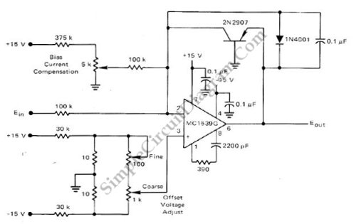
This low-cost logarithmic converter is constructed using an operational amplifier (op-amp) and a transistor. The circuit utilizes a Motorola MC1539G op-amp connected to a PNP transistor. The logarithmic converter circuit is designed to convert linear input signals into logarithmic output...
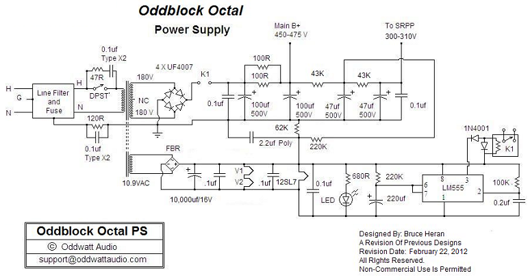
One of the advantages of hosting a hobby website is the opportunity to connect with individuals via email who share similar interests. Since posting Bruce's initial OddWatt project on the site, communication has occurred with numerous DIY hobbyists who...
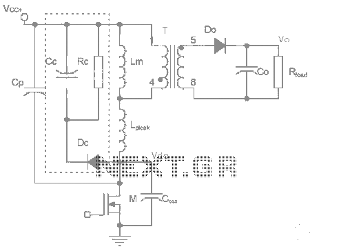
The work process analysis circuit diagram illustrates the use of a flyback converter transformer model. The flyback transformer primarily consists of ideal transformer magnetizing inductance and leakage inductance components. The flyback converter circuit exhibits high-frequency resonance at both ends...
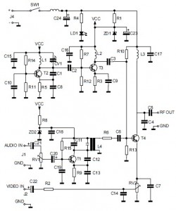
This is the circuit diagram of an audio/video modulator. The circuit converts audio and video signals into a UHF TV signal. It is designed to connect a video signal originating from a camera or other video source to a...
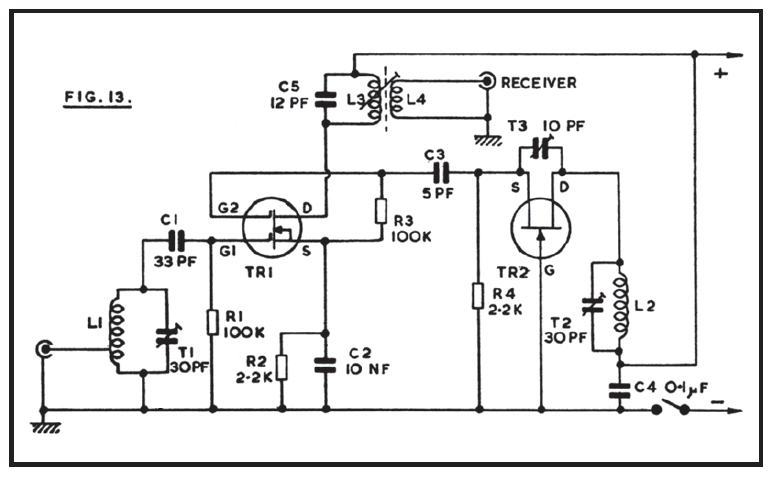
The reception of 2-meter signals typically utilizes a converter and a shortwave receiver, preferably of the communications type, which should exhibit above-average sensitivity and selectivity. This equipment arrangement allows for the conversion of the 144 MHz or other VHF...
Warning: include(partials/cookie-banner.php): Failed to open stream: Permission denied in /var/www/html/nextgr/view-circuit.php on line 713
Warning: include(): Failed opening 'partials/cookie-banner.php' for inclusion (include_path='.:/usr/share/php') in /var/www/html/nextgr/view-circuit.php on line 713