
OddWatt Audio 5751 SRPP / KT88 Push-Pull Monoblock Tube Amplifier Kits
The described tube amplifier circuit showcases a well-thought-out design that emphasizes simplicity and high-quality audio performance. The use of the 5751 valve in the SRPP stage allows for a balance of gain and linearity, while the SIPP output stage enhances efficiency by removing unnecessary components. The incorporation of adjustable biasing provides flexibility for different tube types, appealing to audiophiles who enjoy experimenting with various sound signatures. The choice of components, such as the paper-in-oil capacitor and carbon film resistors, reflects a commitment to audio fidelity. Furthermore, the robust power supply design ensures stable operation, which is critical for achieving optimal performance from the amplifier. Overall, this design not only caters to the needs of hobbyists but also stands as a testament to the enduring appeal of tube amplification in the realm of high-fidelity audio.One of the advantages of hosting a hobby website is that you meet people through email who have similar interests as you. Ever since we posted Bruce`s first OddWatt project on the site I have communicated with a number of DIY hobbyists who have built the various OddWatt amplifiers and have had nothing but very positive comments about the sonic qua
lities of these tube amps. The kits are available in two versions, KT77 rated at 15 watts and KT88 rated at 25 watts which I decided to try. The monoblock tube amp kits arrived about two weeks after placing the order in two double boxed packages, each package weighing about 6.
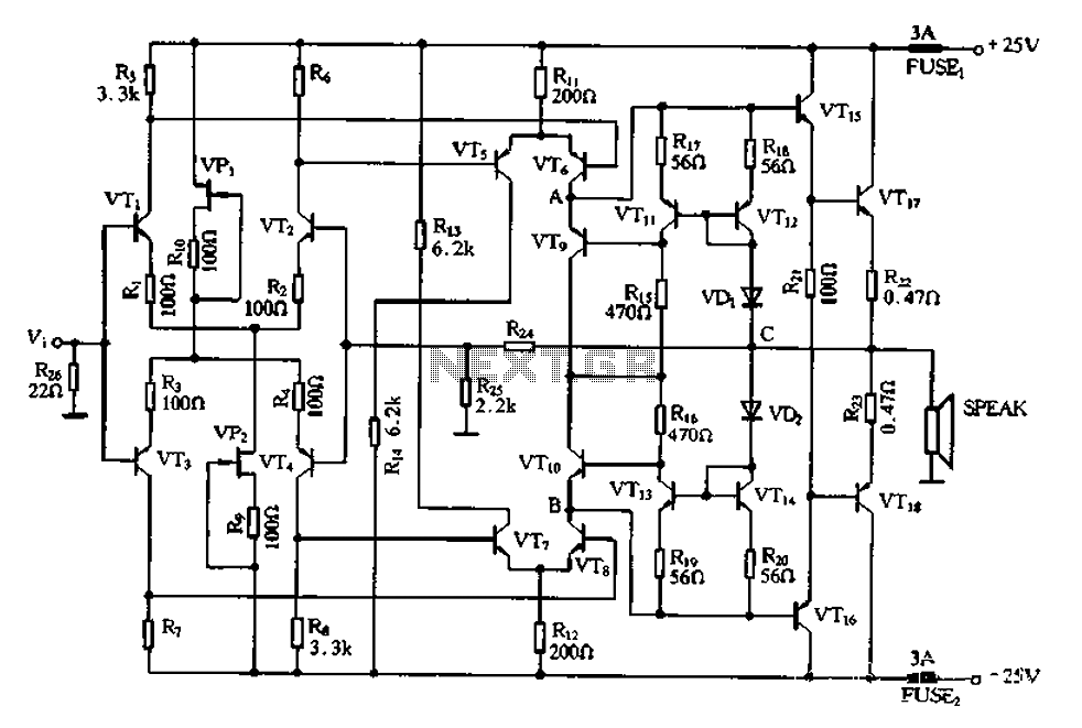
4 kg (14 lbs. ). The kits were well packaged and there was no damage to the contents. Not shown in the photograph is the comprehensive assembly manual which was provided through email. All the parts required to build the tube amp are included. For tools you will need a soldering iron, screwdriver, pliers and wire stripper / cutter. The enclosure is powder coated steel and includes a removable vented cover which can be used to keep curious hands and paws away from the very hot vacuum tubes. The amplifier schematic is shown in Figure 1. Please note that this circuit is © OddWatt Audio and permission to host the schematic on this site has been provided by OddWatt Audio.
You are free to use the schematic for personal, non-commercial use. The voltage gain (input) stage is a common Shunt-Regulated Push-Pull (SRPP) amplifier using a 5751 miniature dual triode valve. Other input tubes can be used in the driver stage, the closest match being a 12AX7 which will provide more gain.
12AU7, ECC82 and ECC802S can also be used but will not be able to provide sufficient gain to drive the KT88 tubes to full power. Bruce indicated that the 5751 provided the best measured performance from the lot of driver tubes. The output stage is a Self Inverting Push-Pull (SIPP) amplifier which is based on the Compact Hi-Fi Power Amplifier by Melvin Leibowitz from 1961.
Unlike conventional push-pull output stages, a phase inverter is not necessary here. Eliminating the phase inverter stage removes an entire active circuit from the signal path. There is only one DC blocking capacitor in the entire signal path of the circuit. The elegance and sheer simplicity of this amplifier circuit will appeal to audio enthusiasts who prefer less components and circuitry in the signal path. A constant current source (CCS) consisting of a LM317HVT voltage regulator IC is used to force the output stage into class-A operation.
The bias current can be adjusted by changing the current setting resistor and this will allow the use of many different power tubes. For those who like to roll tubes, a switch be used to readily allow adjusting the bias current. With the Group "B" tubes (6550, KT88, KT90) the design is conservative and keeps the tubes at about 75-80% of their ratings which will extend the life of the tubes.
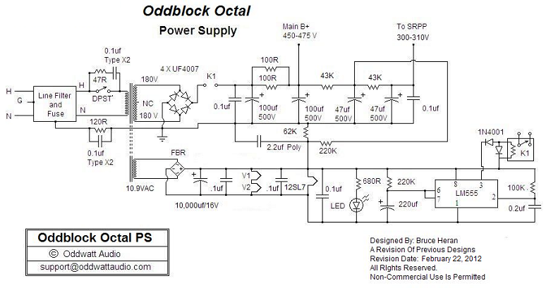
Good quality components are used throughout the amplifier circuit. The DC blocking capacitor is a Russian made paper-in-oil (PIO) type marked K40Y-9 (0. 33uF / 630V) which sounds good and are popular among audio hobbyists. Feel free to experiment with different capacitor or drop in your usual favorite. The resistors are carbon film. The audio output transformer is an Edcor CXPP25-MS-8k, rated at 25 W. A schematic of the power supply is shown below. Like the amplifier schematic, the power supply circuit is © OddWatt Audio and permission to host the schematic on this site has been provided by OddWatt Audio. You are free to use the schematic for personal, non-commercial use. Mains power enters the amplifier through an IEC socket located at the rear of the amp. The IEC socket includes a 3 Ampere fuse and an EMI filter. The power transformer is an OEM manufactured by Edcor with ratings of 180V-0-180V at 250 mA and 12V at 4A.
Power supply capacitors are Panasonic ECG series 500 volt electrolytic a 🔗 External reference
Related Circuits

This design outlines a simple wideband output amplifier suitable for use as a 50-ohm transmission line driver. The circuit is constructed using the CA3140 operational amplifier. When utilized alongside the function generator and sine wave shaper circuits, it delivers...
This circuit features bass boost compensation for a practical power amplifier. It is important to adhere to the specified parameters of the amplifier circuit elements. When switches S1 and S2 are disconnected, the bass boost function can be set...
The direct coupling audio power amplifier utilizes an integrated operational amplifier. There are typically two practical configurations. The first configuration, depicted in (a), features a circuit structure that includes the output of the operational amplifier and a complementary symmetry...
This is a specialized low-voltage version of an audio preamplifier. The emitter voltage of transistor T1 is biased close to half the supply voltage (1.5V) to enable maximum output voltage swing. Both transistors are directly coupled and utilize closed-loop...
Since the volume control is after the gain stage, the preamp can be easily overloaded. I tried to limit the input signal by mounting a 470 k resistor in series with the CD input. A voltage divider is formed...
The CL type circuit is not a power amplifier output capacitance, feedback capacitance, or compensation capacitor amplifier circuit; it operates solely through a transistor (or FET) and a resistor. This circuit can generate feedback, and phase shift elements are...
Warning: include(partials/cookie-banner.php): Failed to open stream: Permission denied in /var/www/html/nextgr/view-circuit.php on line 713
Warning: include(): Failed opening 'partials/cookie-banner.php' for inclusion (include_path='.:/usr/share/php') in /var/www/html/nextgr/view-circuit.php on line 713