
Low-Cost Logarithmic Converter Using Opamp and Transistor
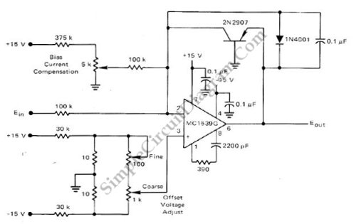
The logarithmic converter circuit is designed to convert linear input signals into logarithmic output signals, which is useful in various applications such as audio signal processing, sensor signal conditioning, and data acquisition systems. The Motorola MC1539G op-amp serves as the core component for signal amplification and processing. This op-amp features low noise and high gain, making it suitable for precision applications.
In this configuration, the op-amp is set up in a non-inverting mode to amplify the input signal. The output of the op-amp is then fed to a PNP transistor, which operates in the active region to provide the logarithmic response. The transistor's base is connected to the op-amp output, while the emitter is linked to the ground through a resistor. This configuration allows the circuit to produce a voltage output that is proportional to the logarithm of the input current, effectively compressing the dynamic range of the input signal.
Additional passive components such as resistors and capacitors may be included in the circuit to stabilize the op-amp, set the gain, and filter noise. The choice of these components will influence the performance characteristics of the logarithmic converter, including bandwidth, linearity, and temperature stability. Proper selection and arrangement of these components are essential to ensure that the circuit meets the desired specifications for its intended application.
Overall, this low-cost logarithmic converter circuit demonstrates an effective use of op-amp and transistor technology to achieve logarithmic signal processing, making it a valuable tool in electronic design and signal conditioning.This low-cost logarithmic converter is built using op-amp and transistor. This circuit uses a Motorola MC1539G op-amp which is connected to PNP transistor. To.. 🔗 External reference
Related Circuits
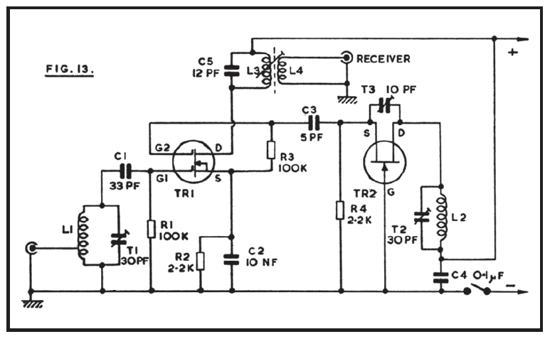
The reception of 2-meter signals typically utilizes a converter and a shortwave receiver, preferably of the communications type, which should exhibit above-average sensitivity and selectivity. This equipment arrangement allows for the conversion of the 144 MHz or other VHF...
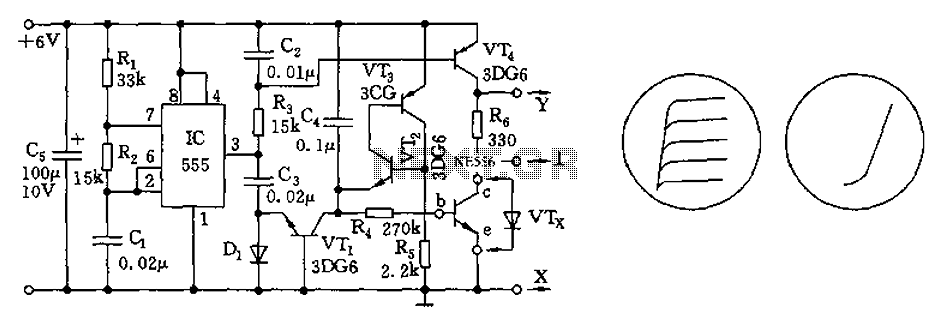
The transistor characteristic curve tracer circuit depicted in Figure 555 illustrates the characteristics of a transistor. It utilizes two voltages: a step wave applied to the base (b) to generate different base currents (Ib), and a sawtooth waveform at...
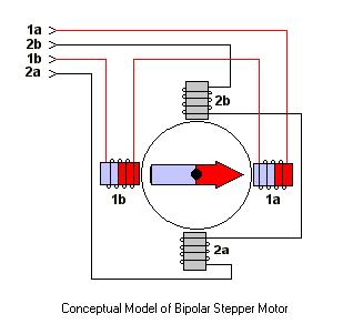
The ULN2003 features high voltage, high current Darlington arrays, each consisting of seven open collector Darlington pairs with common emitters. The ULN2003 is a versatile integrated circuit designed for driving high-current loads such as relays, motors, and lamps. It...
The coil has been enhanced with additional turns, necessitating an improvement in insulation. Epoxy was chosen as the insulating material, with an increased quantity applied over the soldered connections. To ensure the reliability and performance of the coil, the additional...
This is a low-cost accurate square-root circuit. This circuit is used to provide a square-root function with good accuracy. The benefit of this circuit is its affordability and precision. The low-cost accurate square-root circuit typically employs operational amplifiers (op-amps), resistors,...
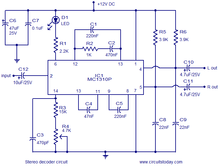
A simple FM stereo decoder circuit utilizing the MC1310P integrated circuit (IC). It operates at 12V and provides a channel separation of 40dB, making it suitable for stereo FM receivers. The FM stereo decoder circuit based on the MC1310P IC...