
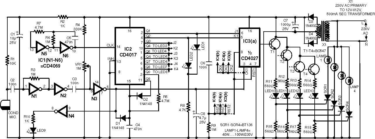
Clap Activated Remote With CD4017 IC
This circuit design addresses the common issue of misplaced remote transmitters in infrared or wireless remote control systems. It introduces an innovative solution that enhances user convenience by allowing control of devices without the need for a traditional remote. The proposed circuit utilizes a combination of a microcontroller, a Bluetooth module, and a smartphone application to enable remote operation.
The microcontroller serves as the central processing unit, managing inputs from the Bluetooth module and executing commands to control various electronic devices. The Bluetooth module facilitates wireless communication between the smartphone and the microcontroller, allowing users to send control signals from their mobile devices. The smartphone application is designed with a user-friendly interface, enabling users to easily navigate and control multiple devices from a single platform.
In addition to the basic control functions, the circuit can be equipped with features such as device status feedback, allowing users to receive real-time updates on the operational status of their devices. This feedback can be implemented through LED indicators or notifications on the smartphone application. Furthermore, the circuit can be designed to operate within a specific range, ensuring that control signals are only transmitted when within proximity of the intended devices.
Overall, this circuit design not only resolves the issue of misplaced remote transmitters but also enhances the user experience by integrating modern technology into traditional remote control systems. The combination of a microcontroller, Bluetooth communication, and a smartphone application represents a significant advancement in the field of remote control technology.The disadvantage of infra-red or wireless remote control is a remote transmitter is often misplaced. This circuit design offers a way to control .. 🔗 External reference
Related Circuits
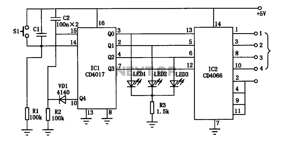
The electronic circuit diagram consists of the CD4017 and CD4066 components configured as a switch circuit. The CD4017 is a decade counter integrated circuit (IC) that can drive up to ten outputs, sequentially activating them based on clock pulses. It...
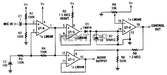
In specific applications, such as transmitters or other communications and control systems, this circuit is designed to be beneficial. It provides both audio output and DC control outputs. Additionally, R9 establishes the control threshold. The circuit in question is versatile...
This circuit below shows a teleremote circuit that enables the switching on and off of appliances through telephone lines. It can be used. The teleremote circuit operates by utilizing telephone lines to control electrical appliances remotely. The primary components of...
The following circuit illustrates a Radio Remote Control Circuit Diagram. This circuit is based on the UM91214B IC. Features include the use of DTMF (dual-tone multi-frequency) technology. The Radio Remote Control Circuit utilizes the UM91214B integrated circuit, which is specifically...
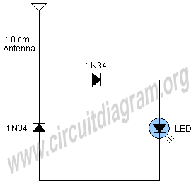
A simple and interesting project schematic for a cell phone signal-activated LED circuit. The circuit will illuminate an LED when a call is made from a cell phone. This cell phone signal-activated LED circuit utilizes a basic principle of detecting...

The board can now be tested. Set the DIP switch to Switch1 ON, Switch2 OFF (15-second delay), Switch3 ON, and Switch4 OFF (4 rings to activate half for switching ON). To switch ON relay 1 (connected to RB0 of...