
40W Fluorescent Lamp Inverter
To calibrate and test the circuit, connect a 2.2 Ohm 1W resistor (R3) in series with the positive supply and attach a 40W fluorescent tube to the high voltage terminals of the transformer. Momentarily apply power; if the tube does not illuminate, reverse the connections of L1. If the tube remains unlit, verify all connections. Once the tube lights, remove the 2.2 Ohm resistor, and the circuit will be ready for operation.
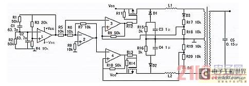
This circuit design is centered around a compact inverter that efficiently converts low-voltage DC into high-voltage AC suitable for fluorescent tubes. The transformer plays a crucial role in this process, with the primary winding responsible for generating a magnetic field that induces a high voltage in the secondary winding. The careful winding of the coils is critical for achieving the desired voltage output, and the use of heat shrink tubing ensures that the windings are insulated from one another, preventing short circuits and enhancing reliability.
The selection of wire gauges for the windings is significant; the primary winding uses thicker wire to handle the higher current, while the secondary winding's finer wire allows for more turns, which is necessary for stepping up the voltage. The calibration process is vital for ensuring that the inverter operates correctly; the inclusion of the resistor serves as a temporary load to facilitate testing without risking damage to the components.
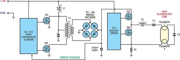
This inverter circuit is particularly useful in applications where standard AC power is unavailable, providing flexibility in powering fluorescent lighting in remote locations or in portable setups. Proper assembly and testing are essential to ensure performance and safety, making this inverter a valuable tool in various electronics and lighting applications.This 40W fluorescent lamp inverter allows you to run 40W fluorescent tubes from any 12V source capable of delivering 3A. This is basically a larger version of the 12VDC Fluorescent Lamp Driver and can be used to light regular or blacklight tubes.
# Wind L1/T1. You will need an AM antenna rod that is about 60mm (2. 5 inches) long to wind T1/L1 on. T 1/L1 are wound on the same core. Shrink a layer of heatshrink over the core to insulate it. Leave 50mm of wire at each end of the coils. Primary: Wind 60 turns of 1mm diameter enamelled copper wire on the first layer and put a layer of heatshrink over it. Feedback: Wind 13 turns of 0. 4mm enamelled copper wire on the core and then heatshrink over that. Secondary: This coil has 450 turns of 0. 4mm enamelled copper wire in three layers. Wind one layer and then heatshrink over it. Do the same for the next two. Transformer/Inductor Winding # Calibrate/test the circuit. To calibrate/set up the circuit connect the 2. 2 Ohm 1W resistor (R3) in series with the positive supply. Connect a 40W fluorescent tube to the high voltage ends of the transformer. Momentarily connect power. If the tube doesn`t light immediately reverse the connections of L1. If the tube still doesn`t work, check all connections. When you get the tube to light remove the 2. 2 ohm resistor and the circuit is ready for use. You will not need R3 again. 🔗 External reference
Related Circuits
The inverter is a device that converts direct current (DC) from a battery or storage battery into alternating current (AC), typically at 220 volts and 50 Hz, producing either sine waves or rectangular waves. It serves as a common...
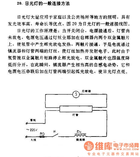
The general connection method for fluorescent lamps is utilized in residential and public lighting applications due to their luminous efficiency and long service life. The general wiring diagram for the lamp is illustrated in Figure 20. The working principle...
Fluorescent tubes consume significantly less energy compared to incandescent lamps and have a much longer lifespan. They provide diffuse, glare-free lighting and generate low heat output. These attributes make fluorescent lighting a preferred option in commercial and retail environments,...

The schematic diagram of a 100W inverter circuit converts a 12V DC input to a 220V AC output. The circuit is built using the CD4047 integrated circuit, which generates a sine wave signal at 50Hz. The power transistor 2N3055...
A guide for creating a remote power switch for a DC to AC inverter. The purpose is to enable the user to turn the inverter on and off remotely. The design of a remote power switch for a DC to...
A varying brightness AC lamp circuit utilizes a silicon-controlled rectifier (SCR) to gradually adjust the intensity of a 120-volt light bulb by controlling the duration of AC line voltage applied to the lamp during each half cycle. The circuit...