
100W Inverter
The 100W inverter circuit operates by converting a 12V DC input into a 220V AC output, making it suitable for various applications, including powering household appliances during outages. The core of the circuit relies on the CD4047 IC, which can be configured to generate either square wave or sine wave outputs. In this configuration, it is set to produce a square wave signal at a frequency of 50Hz, a standard frequency for AC power in many regions.
The 2N3055 power transistor is utilized for its ability to handle high currents and voltages, effectively amplifying the square wave signal generated by the CD4047. The amplified signal is then directed to a step-up transformer, which increases the voltage to the desired 220V AC level. The transformer plays a critical role in isolating the high voltage output from the low voltage input, ensuring safety and functionality.
For applications requiring lower power, such as emergency lighting, the inverter can efficiently power a 40W fluorescent light. The circuit design allows for operation from a 12V battery, making it versatile for use in various settings, including vehicles and off-grid systems. The simplicity of the circuit design, along with the availability of components, makes it an attractive option for both hobbyists and professionals.
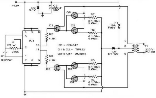
In summary, this inverter circuit is a practical solution for converting DC to AC power, with a focus on ease of construction and component accessibility. Its ability to handle up to 100W of power makes it suitable for a range of applications, while its design emphasizes safety and efficiency.Here the schematic diagram of 100W Inverter Circuit which will convert 12VDC input to be 220VAC output. The circuit built based IC CD4047 to generate sine wave signal 50Hz and then the power transistor 2N3055 will boost the signal so that the signal have high power (high electric current).
Then. With this 500 W cheap inverter inverter 12 V/220 VA C scheme, a constant voltage of 12 V can be converted to AC 220 V. 4047 chip produces a square wave generator of 50 Hz. square wave pulse will be amplified and then fed to the step-up transformer. Calculate the parameters. This is the schematic diagram of inverter circuit for 40W fluorescent light, this is great circuit for emergency lamp. This inverter allows you to power up 40W fluorescent tubes from any 12V source capable of delivering 3A.
The circuit is very simple, inexpensive and easy to build. Please use safety. The scheme of the inverter DC to AC 12 to 220 V. This inverter is suitable for power users who need an alternating voltage of 220 V with a total capacity of up to 100 watts. The inverter consists of a master oscillator (symmetrical multivibrator for VT1, VT2) and the. 12VDC to 220VAC Inverter with timer IC 555 as the wave signal generator, TIP41A and TIP42 as the signal amplifier and the transformer to step up the AC signal from the transistor.
The circuit is very simple and easy to build, the electronic components is very easy to find. Component. We aim to transmit more information by carrying articles. Please send us an E-mail to wanghuali@hqew. net within 15 days if we are involved in the problems of article content, copyright or other problems. We will delete it soon. 🔗 External reference
Related Circuits

The TDA7293, produced by the ST (SGS-THOMSON) company, is a high-power, high-voltage DMOS high-fidelity amplifier integrated circuit (IC) with a rated output power of 100W. It operates at a maximum voltage of 120V. The key specifications include a dual...
This inverter is designed to power appliances such as televisions and stereos while traveling or camping. It converts 12 VDC (volts direct current) to 120 VAC (volts alternating current). This inverter functions by utilizing a series of electronic components to...
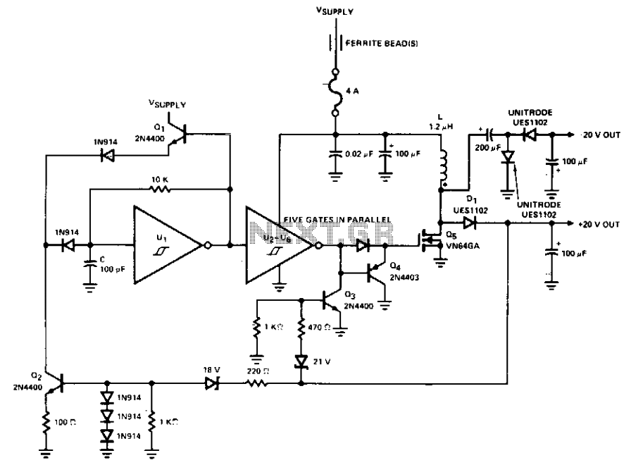
This PWM control circuit generates control pulses for the DMOS power switch in the flyback circuit. The PWM output produces a pulse width that is proportional to the input control voltage, with the repetition rate governed by an external...
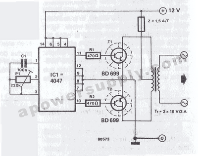
The inverter circuit features the CMOS 4047 as its primary component, converting a 12V DC voltage to a 220V AC voltage. The 4047 operates as an astable multivibrator. A symmetrical rectangular signal is generated at pins 10 and 11,...
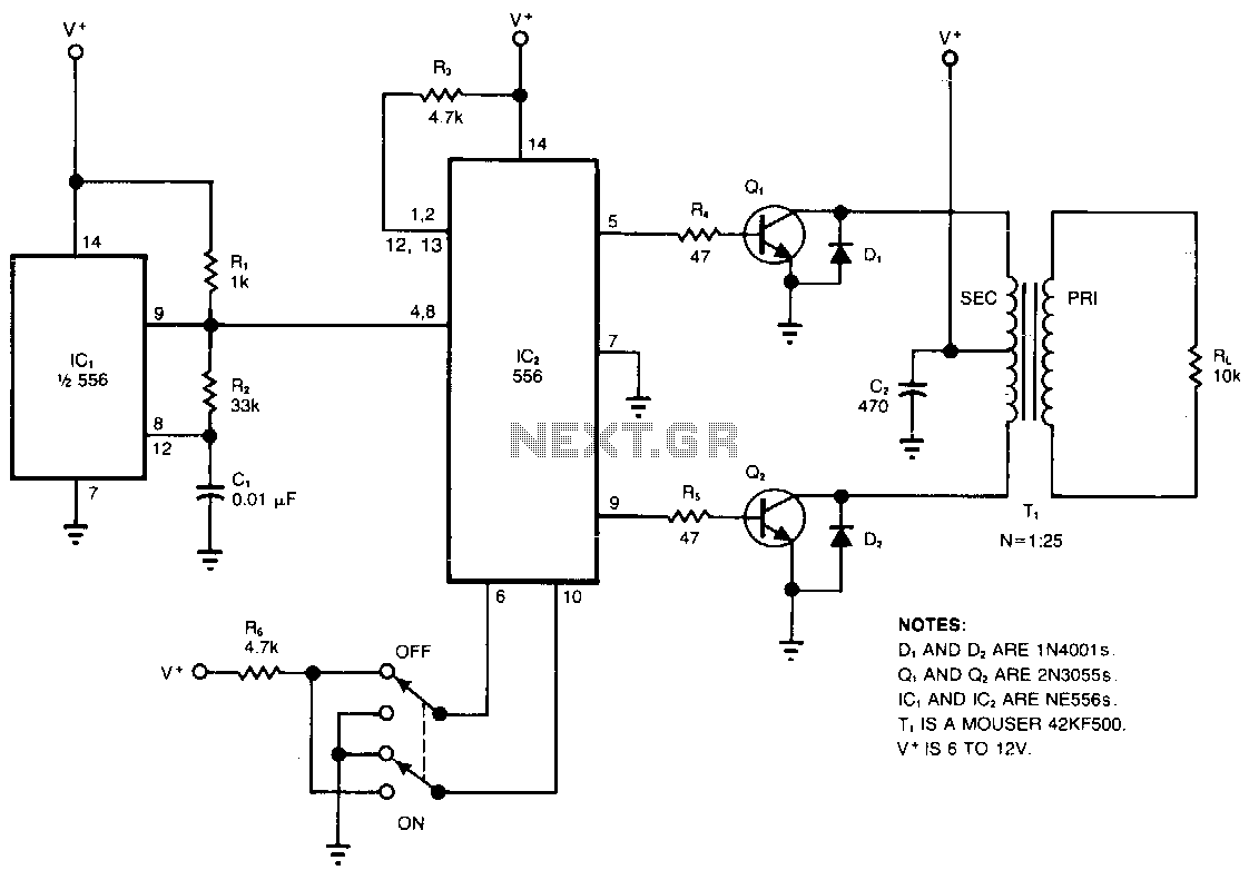
The circuit converts a DC voltage (V+) into a high-amplitude square wave within the audio frequency range. The dual timer, IC2, serves as a cost-effective alternative to traditional transformers for providing complementary base drive to the power transistors, Q1...
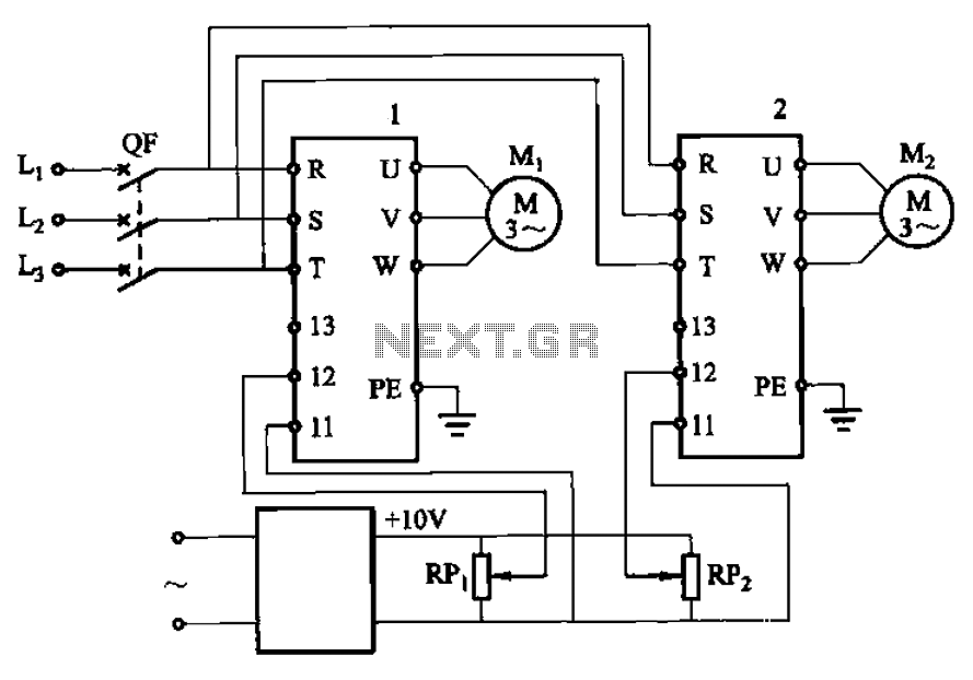
Adjust the potentiometers RPi and RPz to modify the speed of two motors. The circuit utilizes two potentiometers, designated as RPi and RPz, to control the speed of two separate motors. Each potentiometer is connected in a voltage divider configuration,...