
41 LED Flasher Circuit using 555 IC

The circuit employs a 555 timer in astable mode, which generates a continuous square wave output. This output can be used to drive multiple LEDs in a flashing or fading pattern, depending on the resistors and capacitors selected in the timing network. The frequency of the output can be adjusted by varying the values of the resistors (R1 and R2) and the capacitor (C1) connected to the 555 timer.
In this configuration, the output from pin 3 of the 555 timer is connected to the anodes of the LEDs, while the cathodes are connected to ground through appropriate current-limiting resistors. This ensures that each LED receives a safe amount of current, preventing damage. The timing cycle can be modified by changing the resistor and capacitor values, allowing for customization of the LED flashing rate.
Additionally, a potentiometer can be integrated into the circuit to provide a variable resistance, allowing for real-time adjustments to the flashing speed of the LEDs. This feature enhances the usability of the circuit for various applications, such as decorative lighting or visual indicators. The overall simplicity of the design makes it suitable for beginners in electronics, while still providing a platform for more experienced users to explore timing circuits and LED control.I made this as a quick project I made to use a lot of the LEDs I recently got. It basically connects via a 555 8 pin IC and allows for adjusting the t.. 🔗 External reference
Related Circuits

Simple two-wire remote monitoring unit with a three-LED level display, powered by a 9V battery. The entire project was developed at the request of a friend. The remote monitoring unit is designed to provide a straightforward solution for level indication...

The figure illustrates the circuit diagram of a multi-tone alarm, which fundamentally operates as an amplifier circuit. The core component of this circuit is the dual. The multi-tone alarm circuit is designed to produce various sound tones, enhancing its alerting...
A collection of guitar fuzz, preamp, and operational amplifier (op-amp) electronic circuits and schematics designed for various guitar effects and distortion effects. This compilation includes a diverse range of electronic circuits that cater to guitarists seeking to enhance their sound...
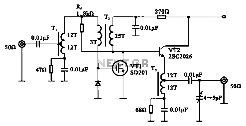
A broadband amplifier circuit utilizing a negative feedback amplifier configuration is presented. This circuit employs transformer coupling and a combination of amplifying sections and field-effect transistors (FETs). The input signal is applied to the center tap of the transformer...
This room light controller project automatically uses a microcontroller to manage a visitor counter, providing a reliable circuit for controlling the room lighting. The room light controller circuit integrates a microcontroller that processes inputs from a visitor counter. This setup...
The objective is to transmit additional information through the distribution of articles. Please contact us via email at [email protected] within 15 days if there are any issues related to article content, copyright, or other concerns. Prompt action will be...