
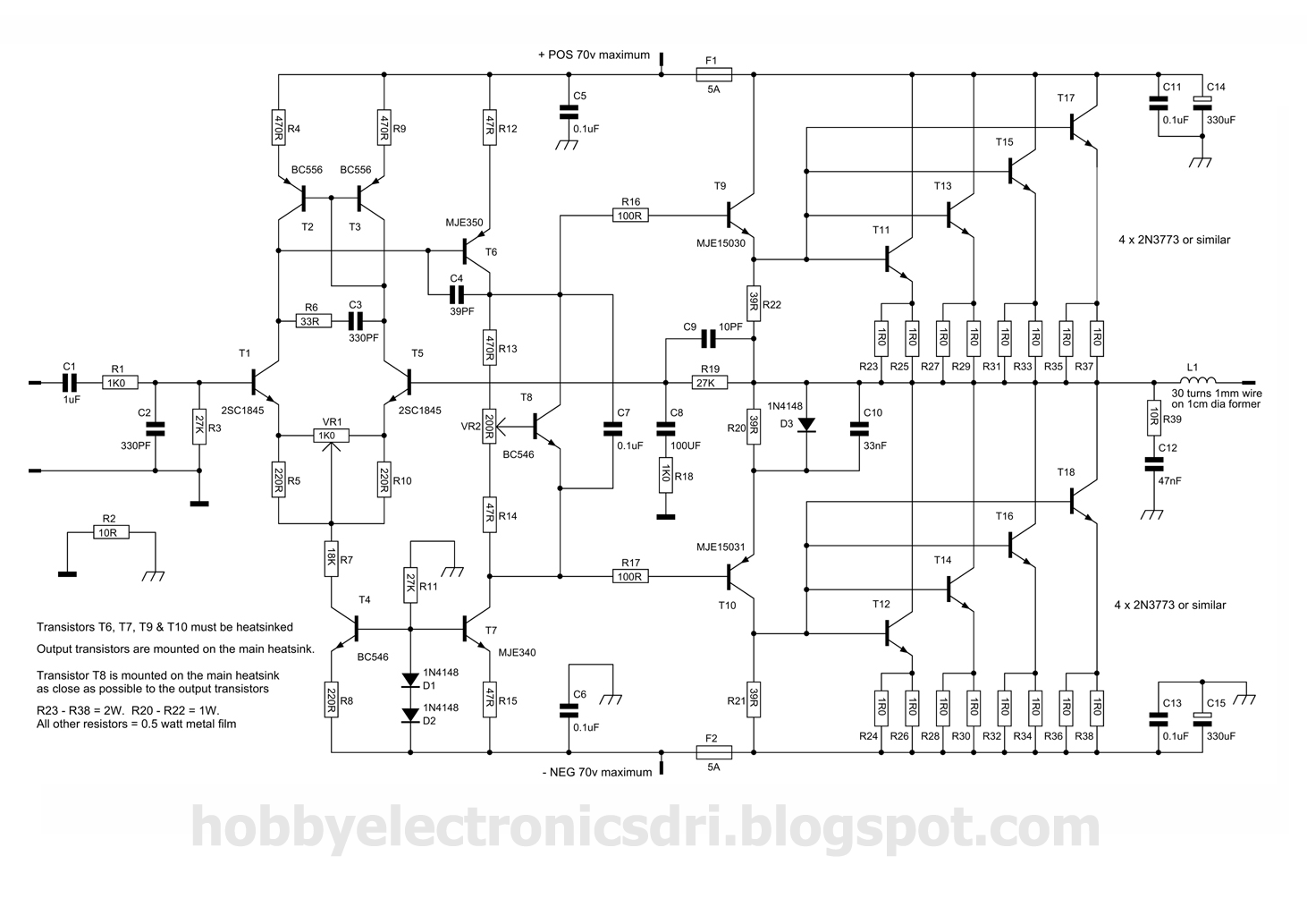
45 Watt Class-B Audio Power Amplifier
The described circuit leverages a discrete-components operational amplifier to drive a complementary common-emitter output stage, optimizing performance for audio applications. The Class B configuration is pivotal, as it allows for efficient power handling by ensuring that the output transistors operate only when necessary, thereby minimizing heat generation and improving overall efficiency. The op-amp's ability to provide output current at lower levels ensures that the circuit remains responsive and dynamic, while the engagement of the power transistors at higher output levels enhances the amplifier's capability to deliver significant power without distortion.
The quiescent current of the op-amp is crucial in biasing the external transistors, which facilitates a smoother transition during the crossover region. This design minimizes the audible artifacts typically associated with crossover distortion, a common challenge in amplifier design. The modification from a Class A to a Class B output stage is significant, as it allows for improved thermal performance and efficiency, particularly in high-power applications.
The transformer specifications indicate a robust power supply capable of supporting two amplifiers with substantial output power, making this circuit suitable for various applications, from home audio systems to professional musical instruments. The low distortion figures at specified output levels demonstrate the circuit's fidelity and suitability for high-quality audio reproduction.
In summary, this discrete-components op-amp design presents a versatile solution for audio amplification needs, effectively combining efficiency, power, and sound quality, making it an ideal choice for both high-fidelity audio applications and musical instrument amplification.These goals were achieved by using a discrete-components op-amp driving a BJT complementary common-emitter output stage into Class B operation. In this way, for small output currents, the output transistors are turned off, and the op-amp provides all of the output current.
At higher output currents, the power transistors conduct, and the contribut ion of the op-amp is limited to approximately 0. 7/R11. The quiescent current of the op-amp biases the external transistors, and hence greatly reduces the range of crossover. The idea sprang up from a letter published on Wireless World, December 1982, page 65 written by N. M. Allinson, then at the University of Keele, Staffordshire. In this letter, op-amp ICs were intended as drivers but, as supply voltages up to +/- 35V are required for an amplifier of about 50W, the use of an op-amp made of discrete-components was then considered and the choice proved rewarding.
The discrete-components op-amp is based on a Douglas Self design. Nevertheless, his circuit featured quite obviously a Class A output stage. As for proper operation of this amplifier a Class B output stage op-amp is required, the original circuit was modified accordingly. Using a mains transformer with a secondary winding rated at the common value of 25 + 25V (or 24 + 24V) and 100/120VA power, two amplifiers can be driven at 45W and 69W output power into 8 and 4 Ohms respectively, with very low distortion (less than 0.
01% @ 1kHz and 20W into 8 Ohms). This simple, straightforward but rugged circuit, though intended for any high quality audio application and, above all, to complete the recently started series of articles forming the Modular Preamplifier Control Center, is also well suited to make a very good Guitar or Bass amplifier. Enjoy! 🔗 External reference
Related Circuits
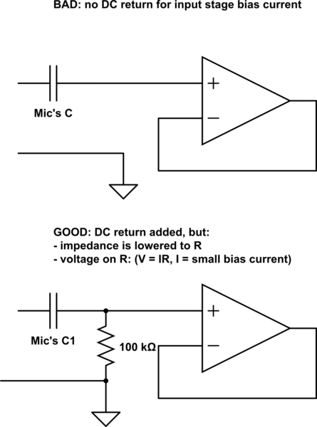
Several KE 4-211-2 Sennheiser microphones were utilized to create a device for acoustic signal analysis. These microphones are connected to a National Instruments data acquisition device via approximately 1 meter long cables, with a sampling rate set at 50...
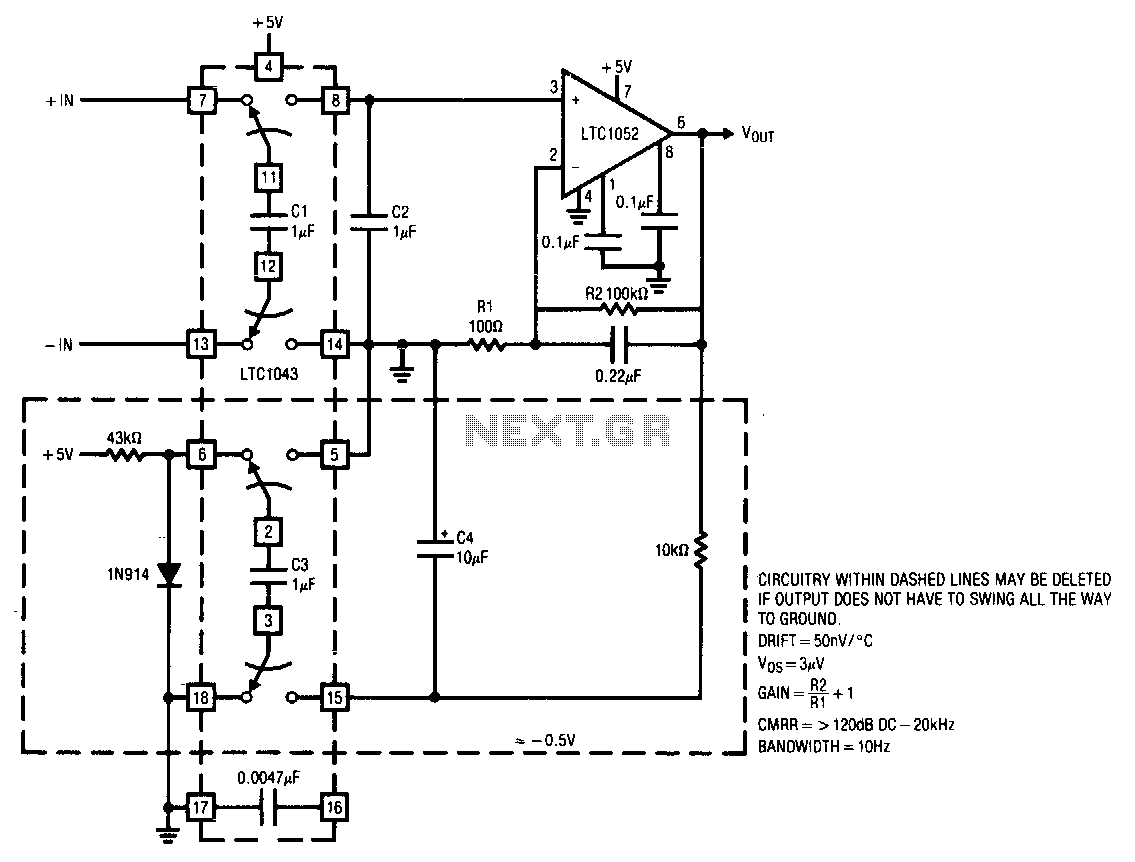
This circuit operates from a single 5 V power supply. The LTC1043 switched-capacitor instrumentation building block facilitates a differential-to-single-ended transition using a flying-capacitor technique. The circuit alternately samples the differential input signal and charges the ground-referred capacitor C2 with...
The combination of controller IC LM4651 and LM4652 Class D MOSFET power amplifier IC provides a high-efficiency solution suitable for powered speakers, subwoofers, and car amplifiers. The LM4651 is a fully integrated conventional pulse width modulator (PWM) driver, which...
This amplifier was designed to utilize the otherwise unused TO3 power transistors that many hobbyists possess. With proper construction, the module can achieve high-quality performance and is rated for 300 watts into a 4-ohm load, depending on the power...
This circuit employs switched emitter followers instead of conventional analog switch CMOS chips, resulting in a more effective reduction of crosstalk between channels. It can manage up to 4 Vms with less than -80 dB crosstalk. The circuit design utilizes...
This wideband DTV UHF antenna TV amplifier provides a total gain ranging from 10 to 15 dB within the frequency domain of 400 to 850 MHz. The wideband DTV UHF antenna TV amplifier is designed to enhance signal strength for...
Warning: include(partials/cookie-banner.php): Failed to open stream: Permission denied in /var/www/html/nextgr/view-circuit.php on line 713
Warning: include(): Failed opening 'partials/cookie-banner.php' for inclusion (include_path='.:/usr/share/php') in /var/www/html/nextgr/view-circuit.php on line 713