
audio Microphones disturbed by capacitance
The system consists of several key components: the KE 4-211-2 Sennheiser microphones, a National Instruments data acquisition device, and passive components including resistors and capacitors. The microphones convert acoustic signals into electrical signals, which are then transmitted through cables to the data acquisition device. The choice of a 1-meter cable length is appropriate for minimizing signal degradation, although it is essential to consider the cable's impedance characteristics.
The sampling rate of 50 kHz is suitable for capturing a wide range of audio frequencies, ensuring that the data acquisition system can accurately process the acoustic signals. However, the introduction of a resistor and capacitor creates a low-pass filter effect, which can inadvertently affect the frequency response of the system. The step function disturbance observed during data collection indicates a transient response caused by the sudden change in load impedance when the data acquisition device begins sampling.
When the data acquisition device is inactive, the capacitors in the circuit charge slowly, creating a stable DC offset. Upon activation of data collection, the rapid change in impedance can lead to an abrupt voltage change, manifesting as a step function in the output signal. This behavior can distort the intended frequency spectrum of the acoustic signals being analyzed.
To mitigate this issue, several strategies may be employed. First, ensuring that the input impedance of the data acquisition device matches the output impedance of the microphone circuit can help reduce the impact of impedance mismatch. Additionally, implementing a buffer amplifier between the microphones and the data acquisition device can isolate the microphone output from the input load, thereby maintaining a more stable signal during data collection.
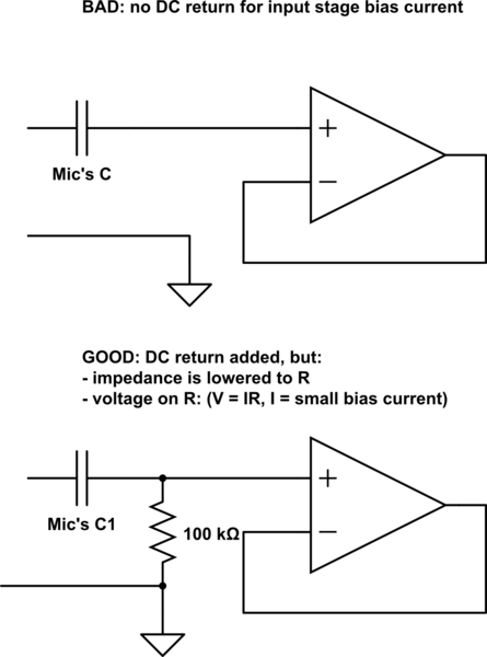
Furthermore, examining the values of the resistor and capacitor in the low-pass filter configuration may provide insight into optimizing the filter's cutoff frequency. Adjusting these values can help minimize the distortion while preserving the desired acoustic signals. Lastly, it may be beneficial to implement a pre-conditioning circuit that stabilizes the signal before it reaches the data acquisition device, ensuring that the system operates effectively under varying conditions.Used several KE 4-211-2 Sennheiser microphones to assemble a device for acoustic signal analysis. They are connected to a National Instruments data acquisition device with ~1 m long cable and sampling rate is set to 50kHz. I`ve added a resistor and a capacitor as described here (2nd page). However after a start of data collection instead of clear acoustic signal I get strong disturbance looking like a step function
in low pass filter. It obviously distorts my frequency spectrum. After investigation I found out that when NI device is not collecting data, capacitors charge slowly and start of collection probably results in dramatic drop of impedance on inputs. What might be a reason for this behavior and what should I do to make it work properly 🔗 External reference
Related Circuits
The project is a variation of the popular POV toy, commonly seen as a beginner electronics project. This year, the decision was made to create a synthesizer kit, incorporating an SPI DAC, audio amplifier, microcontroller, and buttons. Additionally, there...
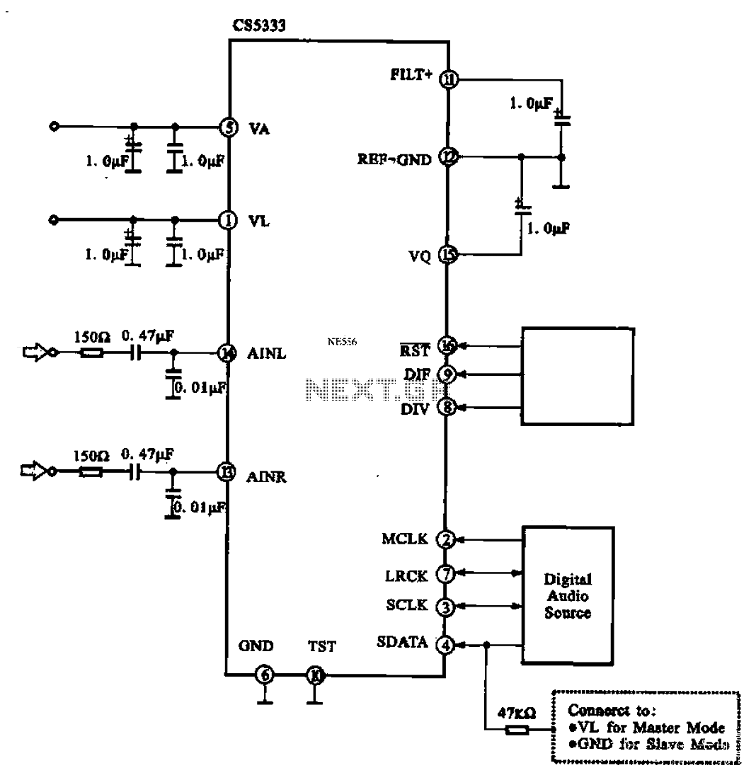
Audio A/D converter circuit configuration using the CS5333 chip, which is a high-performance 24-bit, 96 kHz stereo A/D converter commonly used in digital products. This circuit converts one or more audio signals into a digital signal for processing and...
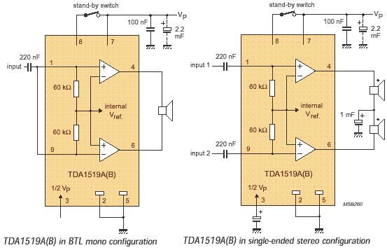
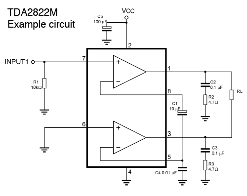
The audio amplifier circuit is based on the TDA1519 amplifier IC, which is designed for audio applications. The TDA1519 has a power output range of 2 to 6 watts. This amplifier is a Class B dual-output type and comes...
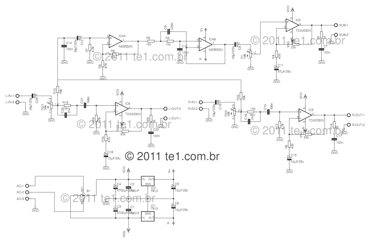
This circuit is a complete application for a 2.1 amplifier system, featuring two satellite speakers for TDA and one subwoofer. It is commonly used in commercial applications to enhance the audio output of computers using a stereo amplifier along...
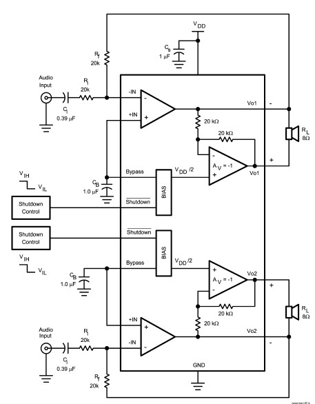
The LM4992 stereo audio power amplifier can be utilized to design a straightforward audio power amplifier project suitable for portable electronic devices. This amplifier circuit is capable of delivering 1 watt of continuous average power per channel to an...
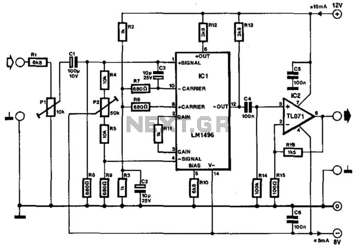
Often, the frequency of a signal must be doubled, and the modulator/demodulator chip LM1496 serves as an ideal basis for this application. From trigonometry, it is well known that 2sin(x)cos(x) = sin(2x) and sin^2(x) = 1 - cos^2(x). These...
Warning: include(partials/cookie-banner.php): Failed to open stream: Permission denied in /var/www/html/nextgr/view-circuit.php on line 713
Warning: include(): Failed opening 'partials/cookie-banner.php' for inclusion (include_path='.:/usr/share/php') in /var/www/html/nextgr/view-circuit.php on line 713