
4511B Common-Anode Display Driver Circuit

In this circuit configuration, the CD4511B is a BCD to 7-segment latch/decoder/driver that can drive a common-anode display. The switching transistors (2N2222 or 2N3904) are employed to control each segment of the display by switching the current on and off. The choice of a common-anode display means that the anodes of all segments are connected to a positive voltage, while the individual cathodes are controlled by the transistors.
The transistor Q1 functions as a switch and is responsible for allowing current to flow through the corresponding segment of the display when activated. The base of the transistor is driven by the output of the CD4511B, which is connected through a current-limiting resistor to ensure that the base current is within the safe operating limits of the transistor. The value of this resistor can be calculated based on the desired base current and the voltage levels in the circuit.
Resistor Rr is crucial as it provides the necessary current to illuminate the display segments. The value of Rr should be determined based on the forward voltage drop of the display segments and the desired segment current, typically around 1 mA. The total current through Rr must be sufficient to drive all segments that may be lit simultaneously, taking into account the maximum number of segments that could be activated at one time.
The gain of the transistor (Hfe) is an important parameter in ensuring that the circuit operates correctly. It should be selected to be higher than the ratio of the segment drive current to the current flowing through resistor R, ensuring that the transistor can adequately switch the required current without entering saturation.
In summary, this circuit effectively utilizes switching transistors to drive a common-anode display, with careful consideration given to the selection of components and their respective values to ensure optimal performance and reliability. The use of a switching transistor (like a 2N2222 or 2N3904) allows use of the CD4511B with a common-anode display. should be chosen to provide about 1 mA to drive Ql and Rr should provide enough current to drive the display.
For this circuit, the transistor gain (Hfe) should be at least the ratio of the segment drive current to the current through R.
Related Circuits
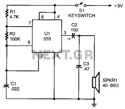
A 555 timer configured as an astable multivibrator is used in this circuit to generate an audio note. The capacitance value can be changed to vary the audio note as desired. The circuit utilizes a 555 timer IC, which...
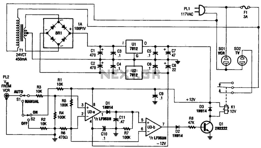
This circuit detects the video signal from the VCR. When the VCR is powered on, the video signal is amplified by U3A to drive Q1, which activates K1. This setup eliminates the need to manually turn on and off...
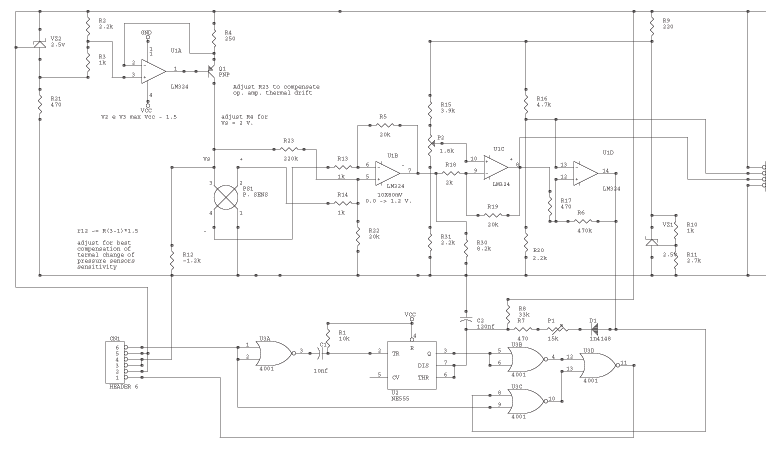
The circuit is powered by the receiver's pack, the current drain is low, especially if compared to drain of servos. U1a VZ2 and Q1 are the current source of the sensor. VZ2 is temperature compensated; use the listed component...
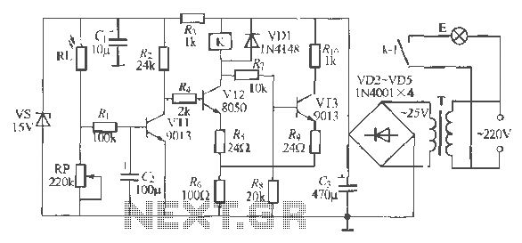
The circuit operates as a light-activated switch that controls white moving lights. It features high sensitivity, stable performance, and good anti-interference characteristics. A photosensitive resistor (RI) is employed to detect ambient light levels. During the day, the resistor exhibits...
The circuit indicates two different water temperature trip points by activating LEDs when the specified temperatures are reached. It is built around the LM2904 dual operational amplifier, which is powered by a 12 V automotive system. A thermistor is...
The internal mute circuit and pre-set gain resistors provide a cost-effective design solution. Output power specifications at both 20V and 24V supplies, along with a low external component count, offer significant value to consumer electronic manufacturers for stereo TV...