
Altimeter Circuit
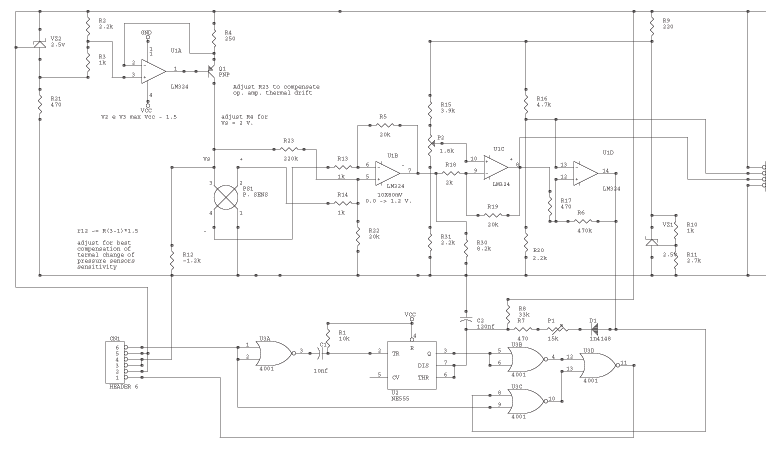
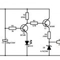
U1d is the comparator; it compares the output of U1c to a reference voltage provided by the group consisting of VZ1, R9, R10, R11, R16, and R20.
The four NOR gates of 4001 are the digital switch; they switch the pulse output (U3d pin 11) from the receiver to the output of NE555. The specifications are more relaxed here; standard parts can be used. P1 adjusts the idle throttle; a single-turn trimmer can be used, although a multi-turn trimmer may be employed but requires a longer adjustment period in the field.
CN1 is the servo in and out; it also carries power for the altimeter. A servo extender (wire with a male connector on one side and female on the other) should be split in the middle, using the two halves as input and output cables while connecting the wires according to the layout of the receiver and servo. CN2 is the meter connector; adjust the voltage between pin 2 and 3 to be equal to the required trigger altitude, and this should be done just before starting the engine. Before soldering, measure the resistance between pins 1 and 3 of PS1 using a good multimeter; R12 must be about 1.5 times the measured resistance; the value printed on the circuit is only indicative.
It is advisable to double-check the entire circuit and have a second person verify the work quality, including soldering, insulation, and fastening of components to the PCB. Power on the circuit and check for any smoke; if there is none, proceed. Measure the voltage between pin 3 and 1 of PS1; it should be approximately 2 volts (1.8 - 2.3 can be acceptable). If the voltage is near 0 or near the power supply, check all connections again. Adjust R4 as necessary (higher R4 leads to higher voltage). Connect a millivoltmeter between pin 2 and 3 of CN2, and adjust P2 to read 50-100mV. As the altitude changes, there should be a corresponding change in reading, approximately 1mV for each meter.
For thermal adjustments, disconnect R13 from PS1 pin 4 and connect it to PS1 pin 2 (short the input of the op-amp together) to initiate a thermal cycle. This involves placing all components except the battery and millivoltmeter in a refrigerator for 15 minutes, recording the reading, then placing everything in free air and repeating the process. Heat the components to 50 degrees Celsius (conversion may be necessary) and repeat the readings. Adjust R23 to minimize drift and continue this cycle until satisfactory results are achieved; the quality of the results will correlate with the patience exercised during this process.
In some instances, R23 may need to be disconnected from pin 5 and connected to pin 6 of U1b. After reconnecting R13 to PS1 pin 4, reconnect the millivoltmeter and readjust P2. Repeat the thermal cycle with more precision, utilizing a thermometer this time, and plot the output readings against temperature between 0 and 40 degrees Celsius. Adjust R12 for minimal drift by replacing it and comparing plots; if the second plot shows improvement, it indicates progress in the calibration process.The circuit is powered by the receiver's pack, the current drain is low, specially if compared to drain of servos. U1a VZ2 and Q1 are the CURRENT source of the sensor VZ2 is temperature compensated, use the listed component except for Q1 there you can use any pnp silicon transistor, resistor must be metal oxide 2%(better) or 5%.
R4 must be adjusted to obtain about 2 Volt between pin 3 and 1 of Pressure Sensor, do not replace it with a trimmer, replace the resistor, the DDP is not important, its stability IS VERY IMPORTANT. PS1 is the pressure sensor, R12 (METAL!) is there to compensate its thermal drift (See later). U1b is the first amplifier, adjust R23 to compensate its thermal offset drift; resistors R5 R13 R14 R22 MUST BE METAL 1%.
U1c give more amplification and add a voltage proportional to the trigger altitude, to be set using P2. Use metal resistor also here, p2 must be a GOOD quality miniature 10 turn trimmer, do not use cheap part here.
The gain can be adjusted replacing R19, the value given set the output to be 1mV = 1 meter if you want 1 mv = 1 foot you must set R19 =~ 60k. U1d is the comparator, it compares the output of U1c to a reference voltage provided by the group VZ1 R9 R10 R11 R16 R20.
The four NOR of 4001 are the digital switch, it switch the pulse output (U3d pin 11) from receiver to the output of NE555; the specs are more relaxed here you can use standard part. P1 adjust the idle throttle, you can use a single turn trimmer, multiple turn trimmer can be used but requires a longer time to adjust on the field.
CN1 is the servo in and out, it carries also the power for the altimeter. Get a servo extender (wire with a male conn. in one side and female in the other), split it in the middle, use the two half as input and output cable, obviously connect the wires according to the disposition of your rx and servo. CN2 is the meter connector, adjust the voltage between pin 2 and 3 to be equal to the trigger altitude required DO THIS JUST BEFORE STARTING THE ENGINE.
Before soldering it, measure the resistance between pins 1 and 3 of PS1, use a good multimeter, R12 must be about 1.5 times the measured resistance; the value printed on the circuit is only orientative. Double check all the circuit, ask a friend to repeat the check for you. Check also the quality of the work: soldering, isolations, fastening of part to pcb, etc. Power on, look for smoke....no smoke? OK go on. Check the current source VZ2 U1a etc. measure the voltage between pin 3 and 1 of PS1: it must be about 2 Volt (1.8 - 2.3 can be ok) if it near 0 or near power check all again, else adjust (replace or mount one resistor in parallel) R4 (higher R4 higher Voltage).
Connect a millivoltmeter between pin 2 and 3 of cn2, adjust P2 to read 50-100mv, going up and down the stairs you must see the reading change, about 1mV each meter. First Thermal adjust: disconnect R13 from PS1 pin 4 connect it to PS1 pin 2, (short the input of OpAmp together) and start a thermal circle.
For thermal circle i mean: put all but battery and millivoltmeter in the refrigerator, wait 15 minutes record the reading and, put all in free air wait ... record the reading, warm all to 50 Centigrades (please do you the conversion ...) (use a table light for this) and repeat.
Modify R23 to minimize the drift, repeat all the circle until you are satisfied by result (the quality of the result is proportional to your patience). In some cases r23 must be disconnected from pin 5 and connected to pin 6 of U1b. Reconnect R13 to PS1 pin 4, reconnect the millivolmeter and re-adjust P2, repeat the thermal cycle, but more accurately (now you need a thermometer) plot the output reading versus temperature between 0 and 40 Centigrade.
Adjust R12 for minimum drift: this means replace R12, repeat all and compare the plots if the second is better you are going in the correct direction etc. 🔗 External reference
Related Circuits
The circuit schematic is straightforward. Information regarding the assembly and testing of circuits is not provided, as there are many instructional resources available. The circuit schematic in question is designed to be simple and user-friendly, allowing for ease of understanding...
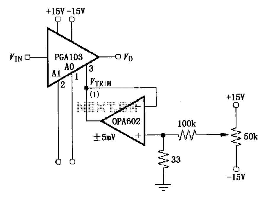
The PGA103 offset voltage correction circuit is designed to minimize the offset voltage for the PGA103 laser correction, ensuring that the gain for three typical offset voltage levels (relative to input) remains below 200 V. Each gain is associated...
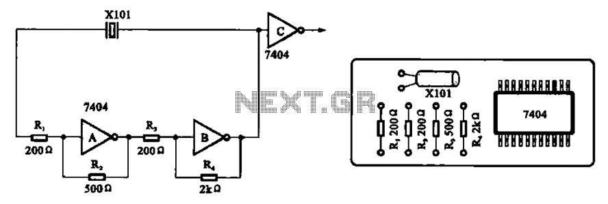
A clock oscillator is commonly utilized in digital signal processing circuits and microprocessor circuits. Digital signal transmission and signal processors necessitate a clock, which serves as the system's timing signal, while the data signal functions as a synchronization signal....
A device designed to locate a mobile phone by emitting intermittent flashes and beeps, indicating the presence of an active mobile phone. This circuit activates even when the mobile phone is in silent mode, making it effective for detecting...
Aux Send is an in-studio performance web show and podcast dedicated to showcasing unique, diverse, and talented independent musicians. Aux Send serves as a platform for independent musicians, providing them with an opportunity to perform and share their artistry in...
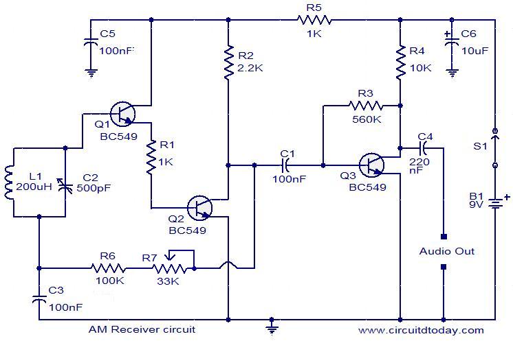
Circuit diagram of a modulator circuit in a transmitter and receiver of amplitude modulation. The modulator circuit in an amplitude modulation (AM) transmitter and receiver plays a crucial role in the process of encoding information onto a carrier wave. In...