Easy street light control circuit
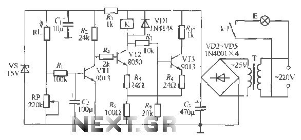
The circuit operates as a light-activated switch that controls white moving lights. It features high sensitivity, stable performance, and good anti-interference characteristics. A photosensitive resistor (RI) is employed to detect ambient light levels. During the day, the resistor exhibits low resistance, allowing the transistor (VT1) to conduct. This results in a low collector voltage, which prevents the emitter-coupled transistor (VT2) from turning on, thereby keeping the relay (K) inactive and the lights off. As evening approaches and ambient light diminishes, the resistance of RI increases, causing insufficient current to maintain VT1's conduction. Consequently, the collector output of VT1 rises, triggering VT2 to conduct, which turns off VT3 and activates relay K, illuminating the lights. An adjustable resistor (RP) allows for fine-tuning of the light control, ensuring appropriate brightness levels. A snubber circuit is included to prevent malfunctions due to brief exposure to light. The circuit is powered by a 220V/25V, 5VA transformer, ensuring minimal heat generation. The relay used is a JQX-13F, capable of handling DC24V and AC220V loads.
The circuit design employs a photosensitive resistor (RI) as the primary sensor for detecting ambient light conditions. This component is crucial for the circuit's functionality, as it modulates the resistance based on light exposure. In bright conditions, the low resistance of RI allows for adequate current flow through VT1, keeping it in a conductive state. This state maintains a low voltage at the collector, which prevents the subsequent transistor (VT2) from activating, thus ensuring that the relay (K) remains off and the connected lights do not illuminate.
As the evening falls and light levels drop, the resistance of RI increases, leading to a reduction in current through VT1. This change causes the transistor to turn off, resulting in a higher voltage at the collector. This voltage is sufficient to trigger VT2, which in turn deactivates VT3. The deactivation of VT3 allows relay K to engage, closing its contacts and powering the lights.
The inclusion of an adjustable resistor (RP) provides flexibility in controlling the sensitivity of the circuit. This feature allows users to tailor the light activation threshold according to specific requirements or preferences, ensuring optimal performance in varying lighting conditions.
To enhance the reliability of the circuit, a snubber circuit is integrated. This component is designed to mitigate the effects of transient signals that may occur due to sudden changes in light exposure, such as passing clouds or brief interruptions caused by objects obstructing the light sensor. By preventing these transients from affecting the circuit's operation, the snubber circuit ensures stable performance and reduces the likelihood of false triggering.
The power supply for the circuit is managed by a transformer rated at 220V/25V with a power capacity of 5VA. This transformer is selected for its efficiency and minimal heat generation during operation, contributing to the overall longevity and reliability of the circuit. The relay used in this design, the JQX-13F, is capable of handling both DC and AC loads, making it suitable for various applications where light activation is required. The relay's specifications ensure that it can manage the power demands of the connected lighting system while providing safe and effective operation.Pi is a good light can throw white moving lights circuit, it has a high sensitivity, stable performance and anti- interference good performance characteristics. Daytime photosensitive resistor RI. Illuminated by natural light exhibits low resistance, the transistor VT1 conduction, its collector is low, so the emitter-coupled trigger off the VT2, VTZ turned on. Relay K is not action, not bright lights E. Evening dark to a certain extent , due to RI. Feeling light line weakened resistance becomes large, the current is insufficient to sustain VT1 conduction, VT1 collector output provider level, emitter-coupled trigger flip that wr2 conduction, VT3 cutoff relay K close friends, close contacts kl road UE lit hair light.
RP can change the electrical adjustment of the foot light control from the control power, so lights live under appropriate light sculpture made of light into electrical light feet. , (J composition under scrambling pulse snubber circuit to prevent short-term exposure to light at night or day deciduous H, fly paper and other short-term occlusion Taipa prime the circuit malfunction, T use 220V / 25V, 5VA quality power transformer, when requested L Q Oh no heat .K energized sheet j JQX-] 3F, DC24V contact capacity AC, 220V, io / rfJ in power electromagnetic relays.
