
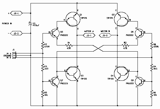
4A H-bridge motor driver using the L298 IC Schematic

The L298 motor driver circuit is designed to control the direction and speed of DC motors and other inductive loads effectively. The L298 IC is a dual H-bridge driver, allowing for bidirectional control of motors. The parallel configuration of the two channels enhances the current capacity, making it suitable for applications requiring higher power levels. The transistors Q1 and Q2 act as control switches; when either control signal W1 or W2 is activated, the corresponding channel of the L298 is enabled, allowing current to flow through the motor in the desired direction.
The decoupling capacitors C1 and C2 are critical for stabilizing the power supply voltage and filtering out high-frequency noise, ensuring smooth operation of the motor. The flyback diodes D1 to D4 are essential for protecting the circuit from voltage spikes generated when the motor is switched off, as these spikes can damage the driver. The choice of diodes should reflect the maximum current expected in the application to guarantee adequate protection.
The direct connection of the motor leads to J1 simplifies the design, allowing for easy integration into various systems. The specified operating voltage range of 9V to 35V provides flexibility for different motor specifications and application requirements. The inclusion of a heat sink is a critical design consideration, as it dissipates heat generated during operation, particularly under high load conditions, thus preventing thermal shutdown or damage to the L298 IC. The successful implementation of this circuit in the ROBOCON 2007 competition demonstrates its reliability and effectiveness in practical applications.This is an implementation of the L298 to drive motors and inductive loads up to 4A continuously. Initially the L298 contains two separate channels, each one capable of driving 2A loads. Connecting them in parallel as in the schematic makes a single 4A driver. The two transistors Q1 and Q2 act as an OR gate enabling the L298 if any of the two signa ls W1 or W2 are high. If both W1 and W2 are low (logic 0), the driver is disabled and provides a high impedance on its output, causing an eventually connected motor to move freely with its inertia. C1 and C2 are 10 nF decoupling capacitors. D1 to D4 are flyback diodes. Their forward current should correspond with the the expected load. The two leads of the motor are directly connected to J1. The circuit can be powered with 9V to 35V Here figure 1, is an implementation of this circuit on a PCB.
This an actual picture of the motor drivers we used in the ROBOCON 2007 competition. Notice how the heat sink is firmly attached to the driver. This protects the IC from eventually burning-up from stall currents. 🔗 External reference
Related Circuits
The 1N4001 is a 1 Amp silicon rectifier with a voltage range of 50 to 1000 volts. It features guaranteed high-temperature soldering, high current capability, a diffused junction, low reverse leakage, and utilizes a void-free molded plastic technique for...
The above shows a home-built digital clock that utilizes Nixie tubes for display. Unlike most contemporary Nixie clocks, this design does not employ transistors or integrated circuits for driving the tubes. Instead, the driving logic is constructed using neon...
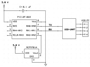
This project outlines a simple and cost-effective method for integrating a digital thermometer and data logging capability into a PC. It utilizes a PIC microcontroller to obtain temperature data from the Microchip MCP9701 sensor and transmits this information to...
H-Bridge This circuit drives small DC motors up to about 100 watts or 5 amps or 40 volts, whichever comes first. Using bigger parts could make it more powerful. Using a real H-bridge IC makes sense for this size of...

A control program typically requires more than simply turning outputs on and off; these actions are triggered by events. Such events are connected to the input of a microcontroller, which determines the subsequent actions. Inputs can originate from various...
In certain applications, it is crucial to allow a motor to operate in only one specific direction, even when the power supply phase sequence is incorrect. This situation may arise due to external factors, such as incorrect wiring after...