
Using Inputs

The described circuit leverages the capabilities of a microcontroller to create a simple yet effective digital input-output interaction. The 16F84 microcontroller is a popular choice for such applications due to its versatility and ease of use. The connection of switch SW1 to pin A0 allows for a straightforward method of detecting user input. When the switch is activated, it creates a low signal on pin A0, which the microcontroller reads as an event. This low signal serves as a trigger for the microcontroller to execute a predetermined response, in this case, turning on or off LED1 connected to pin B0.
In practical terms, the circuit can be implemented on a breadboard or a printed circuit board (PCB), ensuring that connections are secure and reliable. The use of a 32-kHz crystal oscillator provides a stable clock signal for the microcontroller, facilitating accurate timing and processing. If a microcontroller with an internal oscillator, such as the 16F818, is utilized, the design can be simplified by omitting the external crystal and capacitors.
The accompanying code, which is not fully included here, would typically involve initializing pin A0 as an input and pin B0 as an output. The main loop of the program would continuously check the state of pin A0. When a low signal is detected, the program would execute a command to toggle the state of LED1, providing visual feedback to the user. This basic control scheme can be expanded upon with additional logic, such as debouncing the switch input to prevent false triggering due to mechanical bounce.
Overall, this circuit serves as a foundational example of how microcontrollers can be used to create responsive electronic systems, integrating user input with output devices in a seamless manner.A control program usually requires more than turning outputs on and off. They switch on and off because an event has happened. This event is then connected to the input of the microcontroller to "tell" it what to do next. The input could be derived from a switch or it could come from a sensor measuring temperature, light levels, soil moisture, air quality, fluid pressure, engine speed, etc. In this chapter we will concern ourselves with digital on/off inputs. As an example let us design a circuit so that switch SW 1 will turn an LED on and off. The circuit diagram is shown in Fig. 11. 1. This circuit uses the 16F84 microcontroller with a 32-kHz crystal. It can of course also be performed with any of the microcontrollers discussed previously, including the 16F818 using its internal oscillator, in which case the crystal and 2 68pF capacitors are not required. In the circuit diagram SW1 is connected to A0 and LED1 to B0. When the switch is closed A0 goes low or clear, so we wait until A0 is clear. The code for this is: 🔗 External reference
Related Circuits
A teleremote circuit enables the switching on and off of appliances through telephone lines. It can be used to control appliances from any distance, overcoming the limited range of infrared and radio remote controls. The circuit can switch up...
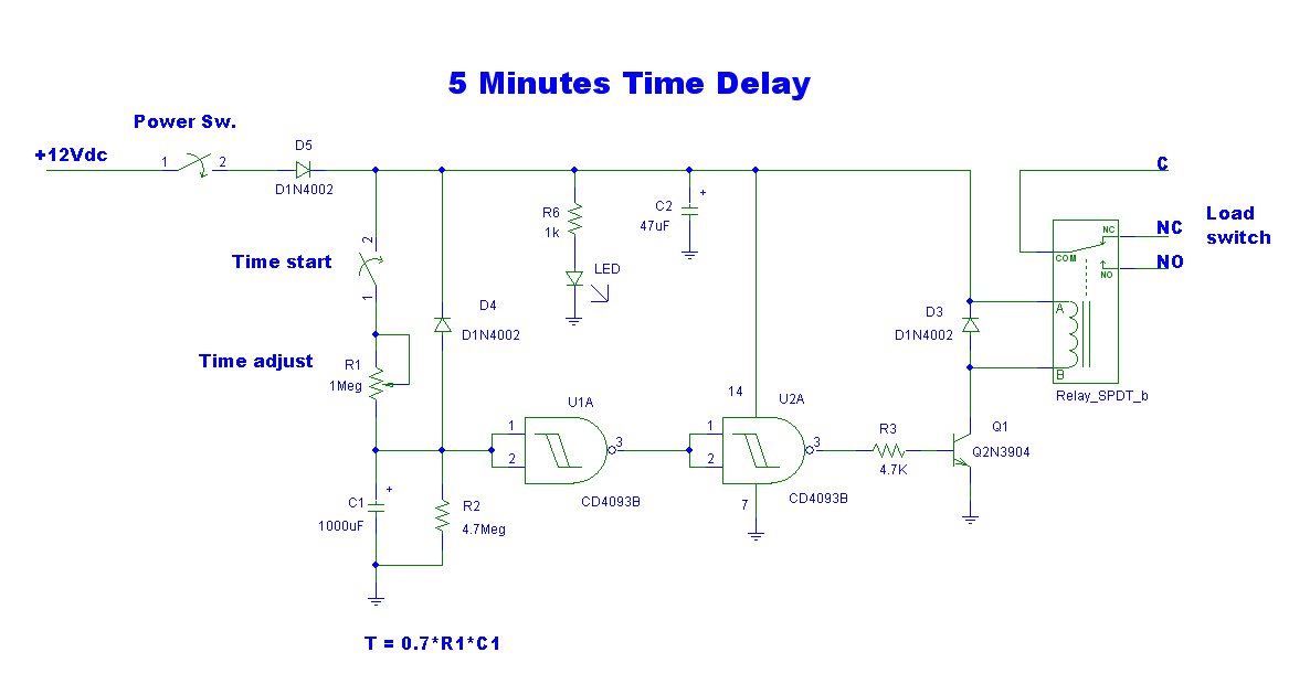
This is a simple delay timer circuit model designed to control the timing of electrical appliances. It provides a delay of approximately 5 minutes before turning off the connected devices. The delay timer circuit functions by utilizing a timing mechanism...
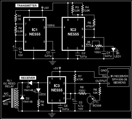
This post discusses a proximity detector circuit primarily utilizing the NE555 integrated circuit (IC). The circuit is designed for burglar alarms based on beam interruption, with the advantage that the transmitter and receiver are contained within the same enclosure,...
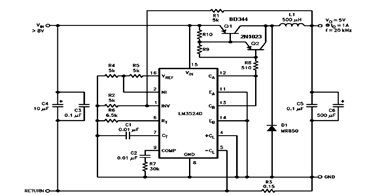
The schematic diagram below illustrates a 5V/1A Step-Down Switching Regulator utilizing the LM2524D Regulating Pulse Width Modulator (PWM). Additional parameters, PC board layout, stuffing diagram, and more information can be found in the LM2524D datasheet. The circuit design features the...
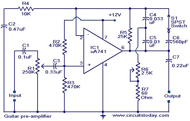
A preamplifier circuit designed for high-impedance electric guitar pickups is presented. This circuit utilizes a uA 741 operational amplifier (IC1) configured as a non-inverting amplifier. The potentiometer R1 functions as a volume control, while potentiometer R6 serves as a...
This project measures the clock pulses supplied to the Timer input of the AVR microcontroller. The Bascom code counts the clock pulses over a duration of 1 second and displays the result. The circuit for this project primarily consists of...