
4W FM Transmitter with 2N2219
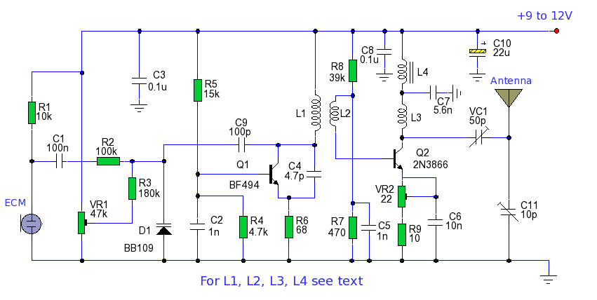
This circuit describes a basic FM transmitter utilizing two 2N2219 transistors (T1 and T2) for amplification and modulation. The use of a heatsink for the 2N2219 transistors is essential to prevent overheating during operation, ensuring stable performance and longevity.
The frequency of the transmitter is regulated by the variable capacitor C4, which allows for fine-tuning of the output frequency to match the desired transmission band. Capacitors C7 and C8 are also variable and are employed to adapt the aerial's resistance, ensuring optimal matching and clarity of the transmitted audio signal. This adjustment is crucial for minimizing distortion and maximizing the quality of the audio received by the radio.
The components of the circuit include resistors R1 and R2, both rated at 10 kΩ, which help set the biasing conditions for the transistors. R3, a 47 Ω resistor, is used for current limiting. Capacitors C1 and C2 (1 nF each) are coupling capacitors that block DC while allowing AC signals to pass, facilitating the modulation of the audio signal onto the carrier wave.
C3 is a larger capacitor rated at 4.7 µF/16V, likely used for power supply decoupling to stabilize the voltage supply to the circuit. The trimmer capacitors C4, C7, and C8, with a range of 0 to 45 pF, are critical for tuning the transmitter's frequency and impedance matching. C5 and C6 (10 pF each) serve as additional coupling or bypass capacitors, while C9 (100 nF) is used for decoupling.
The inductors L1, L3, and L4, wound with a specific number of turns (4, 3, and 5 respectively) on a 7 mm diameter form, are used in the oscillator circuit and for RF amplification. L2 is an RFC (Radio Frequency Choke), consisting of a 1 MΩ resistor wrapped with fine insulated wire, forming a parallel LC circuit that enhances the transmitter's performance by filtering out unwanted frequencies.
The antenna (ANT) is a simple half-wave dipole, which is effective for transmitting the modulated signal over a range. The microphone input (MIC IN) can accept a dynamic microphone or be connected to a cassette player, allowing for versatile audio input options.
Overall, this circuit represents a straightforward yet effective FM transmitter design, suitable for hobbyists and educational purposes in understanding RF transmission principles.This transmitter needs heatsink at 2N2219. With the C4 we regulate the frequency. With their C7, C8 we adapt the resistance of aerial (practically to them we regulate so that it is heard our voice in the radio as long as you become cleaner). Parts: R1, R2=10KOhm R3=47Ohm C1, C2=1nF C3=4,7uF/16V C4, C7, C8=0~45pF trimmer C5, C6=10pF C9=100nF L1=4 turns, 7mm diameter * L3=3 turns, 7mm diameter * L4=5 turns, 7mm diameter * L2=RFC (resistance 1MOhm with wrapped around her inductor of enough coils from fine isolated wire. Scratch of utmost inductor and you stick in utmost the resistance making thus a parallel L-r circuit.) T1, T2=2N2219 ANT=Simple dipole l/2.
MIC IN=Microphone dynamic or other type. (It can also connected to a cassette player unit) 🔗 External reference
Related Circuits
A functional AM transmitter has been completed, primarily based on Phil's Li'l 7 Transmitter design. Achieving oscillation in LC-based transmitters can be challenging without the correct combination of tubes and coils. This transmitter utilizes a 6J5 and a 6SA7...
This transmitter emits an FM signal within the 88 to 108 MHz frequency range, featuring a tone of 19 kHz. This tone can activate the FM MPX pilot carrier indicator, allowing interfacing with external devices. L4 is designed for...
Most IR remotes operate effectively within a range of 5 meters. The complexity of the circuit increases when designing the IR transmitter for reliable operation over longer distances, such as 10 meters. To extend the range from 5 meters...
This transmitter can be tuned to the FM broadcast band, 2 meters, or other VHF bands by changing C5 and L1. The values provided for C5 and L1 will position the frequency within the FM broadcast band. L1 consists...
This set of two circuits forms the basis for a simple light wave transmitter. A laser beam is modulated and directed towards a receiver that demodulates the signal and presents the information, such as voice or data. The assembly...
The power output of many transmitter circuits is low due to the absence of power amplifier stages. The transmitter circuit presented here includes an additional RF power amplifier stage after the oscillator stage, which elevates the power output to...
Warning: include(partials/cookie-banner.php): Failed to open stream: Permission denied in /var/www/html/nextgr/view-circuit.php on line 713
Warning: include(): Failed opening 'partials/cookie-banner.php' for inclusion (include_path='.:/usr/share/php') in /var/www/html/nextgr/view-circuit.php on line 713