
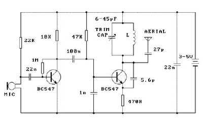
4W FM Transmitters
The described circuit features an L2 RFC (Radio Frequency Choke) with a resistance value of 1MΩ. The inductor, constructed from multiple turns of fine insulated wire, is designed to provide inductance while minimizing losses at radio frequencies. The parallel configuration of the resistor and inductor allows for effective filtering and impedance matching in RF applications.
The inclusion of capacitors C7 and C8 serves to further fine-tune the circuit. These capacitors can be used to create a resonant circuit with the inductor, enhancing the performance of the aerial (antenna) by optimizing the frequency response. This adjustment is crucial for ensuring that the audio signal, specifically the voice, is transmitted clearly over the radio waves.
In practical applications, the values of C7 and C8 may be adjusted to achieve the desired resonance frequency, which is essential for effective communication. The circuit's design emphasizes the importance of both inductive and capacitive elements in achieving optimal performance in RF transmission, highlighting the interplay between resistance, inductance, and capacitance in radio frequency circuits.L2 RFC (resistance 1MOhm with wrapped around her inductor of enough coils from fine isolated wire. Scratch of utmost inductor and you stick in utmost the resistance making thus a parallel L-r circuit. ) With their C7, C8 we adapt the resistance of aerial (practically to them we regulate so that it is heard our voice in the radio as long as you become cleaner).
🔗 External reference
Related Circuits
Antenna is the means by which a wireless operator puts his signal into the space and also through which he picks up the signals of the stations with which he wants to communicate. Hence after having a good Receiver...
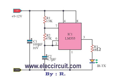
This infrared remote control transmitter circuit exhibits high performance and can be utilized with various infrared receiver circuits. It is designed for ease of construction and cost-effectiveness. Additionally, another circuit is intended for broader applications and requires programming to...
FM Broadcast Audio Transmitter. The circuit includes a frequency-modulated oscillator, an audio preamplifier with pre-emphasis to provide the frequency-modulating signal, and a buffer amplifier to drive the antenna connector. The FM radio pirate introduction to community radio electronics presents...
Place the transmitter approximately 10 feet away from an FM radio. Set the radio to a frequency between 89 and 90 MHz. Walk back to the FM transmitter and turn it on. Separate the windings of the coil by...
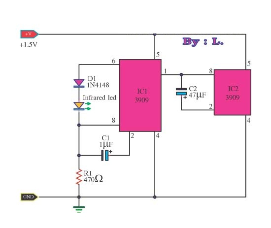
This circuit is an infrared transmitter that operates on a low power supply of 1.5 V. The main components include two LM3909 integrated circuits, which function as an oscillator and LED flasher. Typically, this circuit is utilized as a...
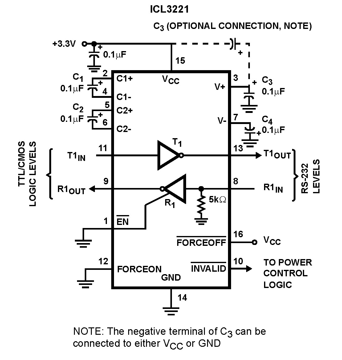
The Intersil ICL32XX devices are powered by 3.0V to 5.5V and function as RS-232 transmitters and receivers, complying with EIA/TIA-232 and V.28/V.24 specifications, even at a supply voltage of 3.0V. These devices are designed for applications such as PDAs,...