
Infrared Remote control transmitters
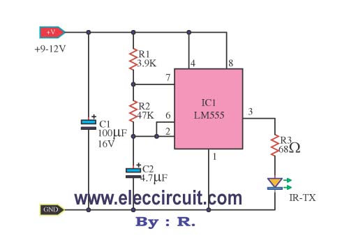
The infrared remote control transmitter circuit is structured around the IC-555 timer, which serves as the central timing element. The timer is configured in astable mode, where the frequency of oscillation is determined by the values of R1, R2, and C2. The output from the IC-555 is a square wave that toggles between high and low states, creating the necessary pulse train to modulate the infrared diode. The duty cycle of this signal is set to 50%, which is essential for ensuring that the infrared light is emitted consistently for effective communication with the receiver.
In applications requiring higher output power, the circuit can be enhanced by adding a power transistor, such as the BD137, which acts as an amplifier. This transistor allows for driving multiple infrared diodes in parallel, thus increasing the overall output power and improving the range of the transmitter. The careful selection of R3 is critical, as it limits the base current to the transistor and prevents overheating or damage to the component.
The incorporation of LED1 serves a dual purpose; it not only provides a visual indication of power to the circuit but can also be used for troubleshooting purposes. If LED1 does not illuminate, it indicates potential issues in the power supply or circuit connections.
The LM3909 integrated circuit, while primarily designed for LED flashing applications, complements the infrared transmitter by allowing for additional modulation effects if desired. The configuration with a 1.5V power supply ensures that the circuit remains low-power, making it suitable for battery-operated devices.
In summary, this infrared remote control transmitter circuit is a versatile and cost-effective solution for applications requiring infrared communication. Its design allows for easy adjustments to frequency and output strength, making it adaptable for various uses in consumer electronics and remote control systems.This is Infrared Remote control transmitter circuit has high performance and can be applied to works with the various infrared receiver circuit. To made easily. And best to save your money. - Then another circuits, is designed to have wider applications. Can be set program that will be must have a beam of infrared light to circuits few times to wo rk. -But in real applications. We need to enter the signal pulse with a frequency of about 5kHz, to the infrared diode, for eliminate the various interference. And reduce the power supplied to the diode. In the first circuits, to be a simple infrared transmitter with IC-555 timer to an oscillator generator at frequency of 5kHz, that is set with R1, R2 and C2.
The output signal will have signal period on-off 1:1 If you want the infrared transmitter that has the signal strength is very high. You can be done by adding the output transistors. Enable With the infrared diodes up to three tubes. Be seen from the circuit, IC 555 use to function frequency generator is 5000Hz as well. The frequency of the circuit is determined by the VR1, R1, R2 and C1, we can customize the frequency by adjusting VR1.
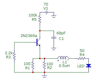
Output of IC is supplied to the transistor Q1-BD137 to drive infrared diodes with high current to 100mA. Risisetars R3 in the circuit should not be less than 3. 9 ohm as it may cause damage to TR1. R4 and LED1 to indicate that the voltage supply to the circuits. This is an infrared transmitters signal circuit that is small size and using a power supply 1. 5V only. by main electronic part are two the LM3909 (a LED Flasher Oscillator IC) Normally, we tend to put it to use as a simple flashing light circuit.
Using a 1. 5V low power supply, it`s working now, Easier to use transistors. The high frequency, it is very simple, just change the device to high frequency only. C1 and R1 is lower the higher frequency. 🔗 External reference
Related Circuits
This article presents basic circuits for pulsing infrared LEDs and low-power visible semiconductor lasers utilizing inexpensive and readily available components. Numerous interesting and practical applications are referenced, alongside several online resources. The focus of the article is on the...
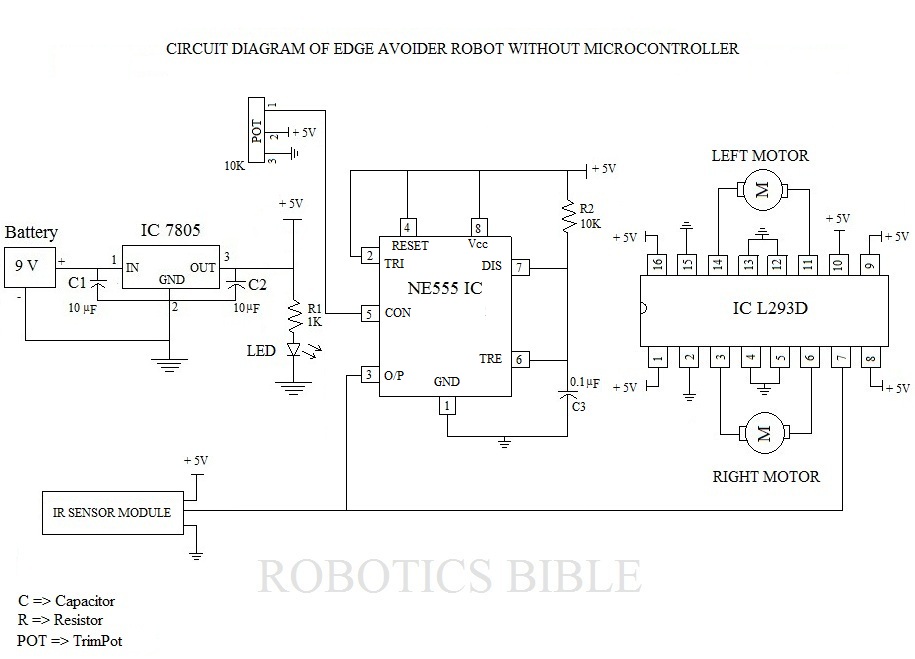
The Edge Avoider Robot (EAR) is a mobile device that detects and avoids areas where there is no surface beneath it. The Edge Avoider Robot (EAR) operates using a combination of sensors and microcontroller technology to navigate its environment effectively....
This simple tone control can be used in many audio applications. It can be added to amplifiers, used as a standalone control module, or even built into new and exciting instruments. Its one IC construction makes it a very...
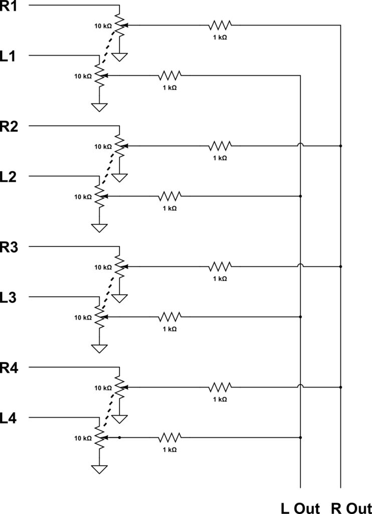
This audio mixer combines multiple audio inputs into a single audio output, equipped with knobs to adjust the volume for each channel. The specific build includes... The audio mixer is designed to facilitate the blending of various audio signals, allowing...
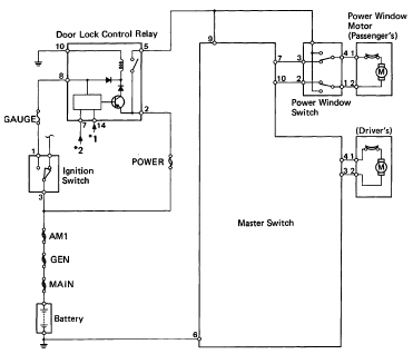
The following circuit illustrates the 1993 Toyota Hilux Pickup Power Window Control System Electrical Circuit Diagram. It is beneficial for both personal use and for mechanics during repairs. Key components include the door lock relay, junction block, power window...
This page shows some methods of track routing control for Stall-Motor type switch machines. The principle method uses a 2 Pole - Multi Position rotary switch while an alternate uses optoisolators and transistors to select the routes. The last...