
5 channel radio remote control
The circuit design integrates a comprehensive approach to remote control functionality, leveraging the TX-2B and RX-2B ICs for effective communication. The TX-2B module is responsible for encoding control signals from the push-button switches, with the internal oscillator frequency set by resistor R7 to optimize transmission efficiency. The Zener diode D1 ensures stable voltage supply to the TX-2B, preventing fluctuations that could disrupt operation. The modulation process, facilitated by transistor Q1 and capacitor C3, ensures that the encoded signal is effectively transmitted over radio frequencies, enhancing the range and reliability of the control system.
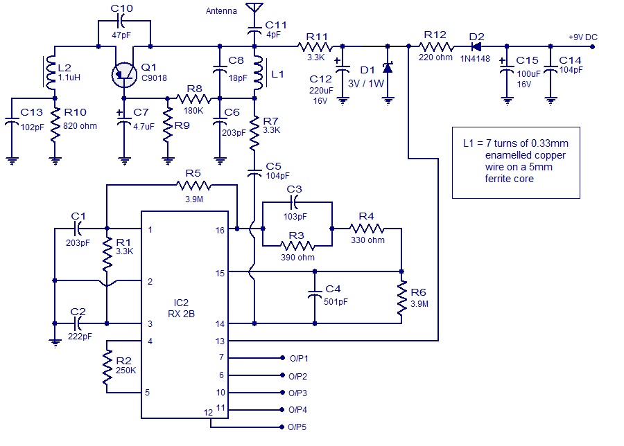
In the receiver section, the RX-2B demodulates incoming signals, with the output states corresponding to the activation of the respective push buttons. The circuit's robustness is further enhanced by the inclusion of various filtering capacitors and protection diodes, ensuring longevity and reliability in diverse operating conditions. The design is versatile, allowing adaptation for various applications beyond toy controls, such as home automation systems, remote lighting, and other remote switching tasks, making it a practical solution for numerous electronic projects.This article is about a simple 5 channel radio remote control circuit based on ICs TX-2B and RX-2B from Silan Semiconductors. TX-2B / RX-2B is a remote encoder decoder pair that can be used for remote control applications. TX-2B / RX-2B has five channels, wide operating voltage range (from 1. 5V to 5V), low stand by current (around 10uA), low opera ting current (2mA), auto power off function and requires few external components. The TX-2B / RX-2B was originally designed for remote toy car applications, but they can be used for any kind of remote switching application. The TX-2B forms the main part of the circuit. Push button switches S1 to S5 are used for activating (ON/OFF) the corresponding O/P channels in the receiver / decoder circuit.
These push button switches are interfaced to the built-in latch circuitry of the TX-2B. Resistor R7 sets the frequency of the TX-2B`s internal oscillator. Resistor R1 and Zener diode D1 forms a simple Zener regulator circuit for providing the IC with 3V from the 9V main supply. C2 is the filter capacitor while C1 is a noise by-pass capacitor. D2 is the power on indicator LED while R6 limits the current through the same LED. S1 is the ON/OFF switch. The encoded control signal will be available at pin 8 of the IC. The encoded signal available at pin 8 is without carrier frequency. This signal is fed to the next stage of the circuit which is a radio transmitter. Crystal X1 sets the oscillator frequency of the transmitter section. R2 is the biasing resistor for Q1 while R3 limits the collector current of Q1. The encoded signal is coupled to the collector of Q1 through C3 for modulation. Transistor Q2 and associated components provide further amplification to the modulated signal. The remote receiver circuit is built around the IC RX-2B. The first part of the circuit is a radio receiver built around transistor Q1. The received signal is demodulated and fed to pin 14 of the IC. Pin 14 is the input of the built in inverter inside the IC. R2 sets the frequency of the IC`s internal oscillator. O/P 1 to O/5 are the output pins that are activated corresponding to the push buttons S1 to S5. Zener diode D1 and resistor R12 forms an elementary Zener regulator for supplying the RX-2B with 3V from the 9V main supply.
C12 is the filter capacitor while R11 is the current limiter for the radio receiver section. Diode D2 protects the circuit from accidental polarity reversals. C15 is another filter capacitor and C14 is a noise by-pass capacitor. 🔗 External reference
Related Circuits

The automatic pump controller eliminates the need for manual operation of pumps used for transferring water from a reservoir to an overhead tank. It activates the pump when the water level in the tank falls below a designated low...
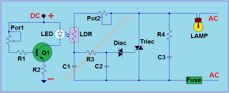
This is another AC light dimmer, with the primary distinction being that its control circuit is isolated from the AC line, making it much safer to use. The circuit can operate on both 120V and 220V AC lines. Note:...
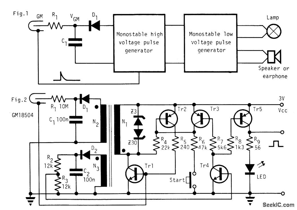
In the absence of radiation, no current is drawn. At normal background radiation levels, the power consumption is extremely low. The instrument may be left on for several months without changing batteries. In this way, the detector is always...
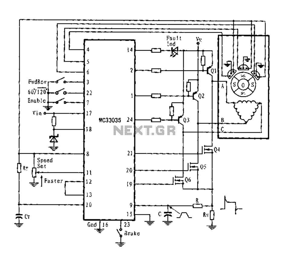
The application circuit is a three-phase full-wave six-step driving circuit for an open-loop motor controller. It features a power switching transistor of the Darlington type, specifically PNP, while the lower power switching transistors are N-channel power MOSFETs. Each device...

This is a circuit design for a PWM speed control circuit for DC motor rotation. The circuit features two functions: Forward-Reverse operation and Regenerative Braking. The control is achieved using a MOSFET. The circuit allows for the control of...
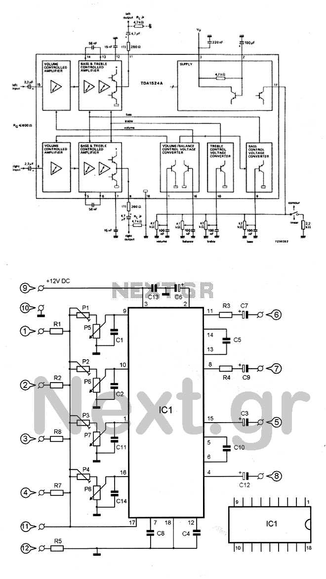
The circuit utilizes the TDA1524 chip, which is an integrated control unit for volume, bass, treble, and balance adjustments. Control is achieved through four potentiometers (P5-P8). The integrated circuit IC1 requires very few external components to operate. Potentiometers P1-P4...