
5 volt ttl voltage monitor

The described device serves as a voltage monitoring and control system, utilizing a low-current window comparator to ensure that the supply voltage remains stable at +5 V. The LTC1042 comparator is pivotal in this application, as it compares the monitored voltage against a precise reference voltage derived from a zener diode. The choice of a 2.5 V reference allows for a symmetrical window around this value, facilitating effective monitoring of voltage deviations.
The window comparator operates by defining a voltage range that the monitored signal must stay within. The reference voltage is established by the zener diode D1, which provides a stable voltage source. The voltage window is determined by the resistor divider formed by R4 and R5, ensuring that the comparator can detect slight variations in the input voltage. The resistor network formed by R2 and R6 scales the monitored voltage down to a level compatible with the comparator's input range, allowing for accurate comparisons.
The output of the comparator is connected to indicator LEDs. The green LED D2 signifies that the monitored voltage is within the acceptable range, providing a visual confirmation of normal operation. Conversely, the red LED D3 serves as an alert, illuminating when the voltage strays outside the defined limits, thereby enabling immediate corrective actions.
Overall, this voltage monitoring device is essential for applications requiring precise voltage regulation and monitoring, ensuring that the system operates within specified parameters. The use of TTL signal levels for output makes it suitable for integration with digital systems, enhancing its utility in various electronic applications.This is a simple device designed to control supply voltage +5 V Monitor provides information signals TTL level, accompanied by the LED display, indicating that stress or deviated from the nominal value, or vice versa, is in a box . The basis of the device is a low-current window comparator IC LTC1042 company Linear Technology. The reference vol tage is 2. 5 V ± 0. 005 V for the middle window created by zener D1 and fed to pin 2 comparator. The width of this window equal to 20% ( ± 10%) of the reference voltage established at pin 5 chip divider R4, R5. The controlled voltage is divided by two resistors R2 and R6, and fed to pin 3 of the chip. Voltage at the terminals 2 and 3 are compared with the established view of the deviation (10%, output 5).
The green LED D2 is illuminated when the voltage is within the desired range. If the voltage is out of range, red LED D3. 🔗 External reference
Related Circuits
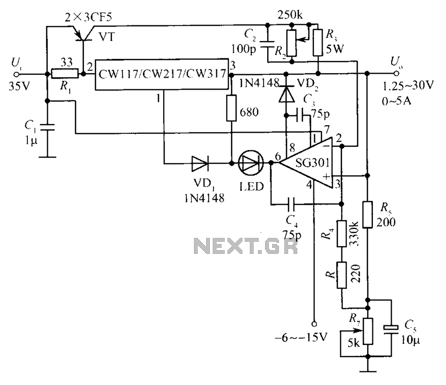
This document presents a diagram of a constant voltage/current power supply box. It is composed of three main components: spread current, constant voltage, and constant current. The design features two 3CF5 power transistors arranged in parallel, functioning as an...
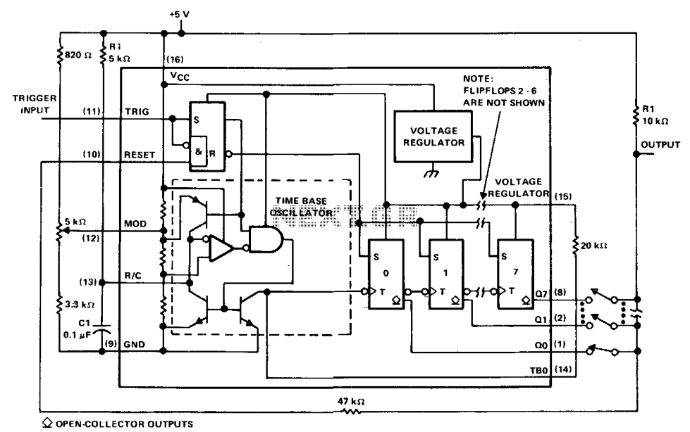
The µA2240 can be easily configured as a programmable voltage-controlled timer with a minimal number of external components. The modulation input (pin 12) allows for external adjustment of the input threshold level. A variable voltage is applied from the...
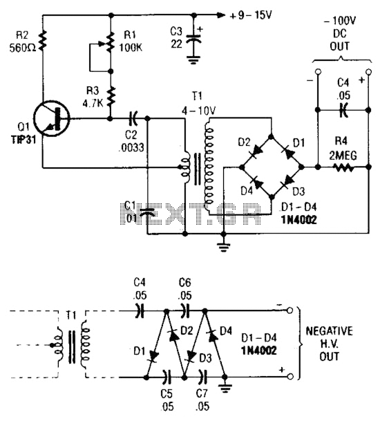
The combination of a Hartley oscillator and a step-up transformer can generate significant negative high voltage, particularly when the voltage output of the transformer is multiplied by the circuit. The Hartley oscillator is a type of LC oscillator that utilizes...
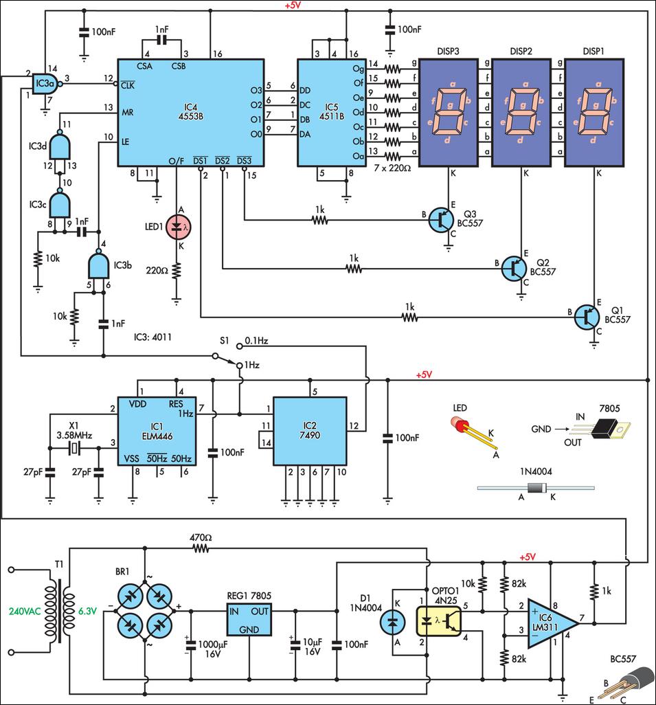
This is a simple frequency counter designed to monitor the 240VAC mains supply. It has a frequency range of 0-999Hz, making it suitable for use with 400Hz equipment as well. Standard TTL/CMOS logic is utilized for the counters and...
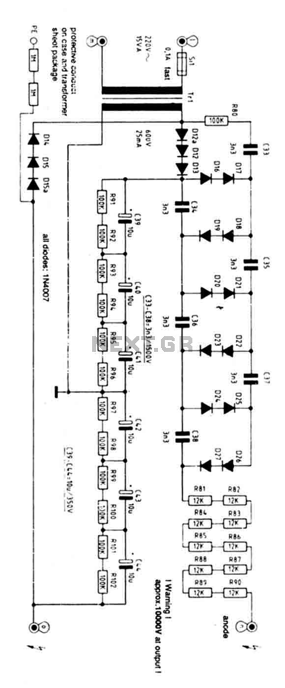
Exercise caution with this power supply as it operates on 220V mains and has an output voltage of 10KV. Characteristics: Supply: 220V AC 50Hz mains, Power: 15 Watts, Ignition Voltage: 8KV. The power supply operates on a standard 220V AC...
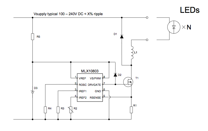
The applications outlined in this document pertain to driving high-power LED diodes. The circuits described can also be utilized in other applications with similar requirements, as long as they adhere to the specifications of the MLX10803. This is a...