
50 Watt power Amplifier
Note: The TIP33C and TIP34C have been discontinued and are generally not available anywhere. A wide range of power transistors will work, but they should be rated for at least 100V, 8A, and 80W power dissipation. Safe area operating curves and good thermal dissipation data are rarely available, so it's a guessing game. The more expensive TO-3 package parts, such as the MJ15003 & MJ15004 will certainly be more than sufficient for replacing the TIP33C & TIP34C. The only really compelling reason to use the TIP33C & TIP34C is because they cost less and come in a TO-218 package, which requires only one mounting hole.
If any of these tests fail, the amplifier is not constructed properly. The easiest and best way to find the problem is through visual inspection.
Turn the variable resistor fully counterclockwise (max resistance). Connect to +/- 24 volt supply with a 200mA current limit. No input and no output connected. Monitor current from the power supply with a current meter. Apply power; if the current is above about 25 mA, shut off immediately! Measure voltage across the 1k resistor connected to the input stage and Vcc. The DC voltage should be about 2 volts, or 2 mA of current through this resistor. For example, if Vcc is at 24 volts, the side of this resistor connected to the 2N5210 transistor ought to be at about 22 volts. Measure the DC voltage on the output line; it should be approximately zero volts. -0.2 volts is probably fine.
Turn the variable resistor slowly until the amplifier's current consumption is approximately 50 mA. Turn slowly and be careful; if the adjustment is turned too far, it could damage the output transistors. Connect an oscilloscope to the output and apply a low amplitude 20 kHz square wave to the input. DO NOT connect any speakers during this test. This test should be done without the 330 pF capacitor installed. The amplifier should output a 20 kHz square wave with very little "ringing" and should not oscillate. Solder the 330 pF capacitor into the circuit. Shut off the power, connect the audio input and a speaker. Make sure the volume is turned all the way down. Apply power; watch the current meter again and shut off the power immediately if the current jumps to something much higher than 50 mA. Slowly turn up the volume and see if the amplifier works. DO NOT turn it up very much; the amplifier should not be operated with a supply less than +/- 30 volts. It should never be used for high volume output without a power supply rated for at least 2 amps of current (8-ohm load). After this initial test with +/- 24V at 200 mA (current limited), only a proper power supply should be used that can provide enough current.
The audio power amplifier circuit is based on a class AB configuration, which allows for efficient amplification of audio signals with minimal distortion. The circuit typically consists of input stage transistors (such as the 2N5210), driver transistors, and output transistors (TIP33C and TIP34C or their equivalents). The input stage is responsible for signal conditioning and initial amplification, while the driver stage increases the current capability to drive the output stage, which consists of power transistors that deliver the final amplified signal to the load (speaker).
The circuit layout should ensure proper thermal management, particularly for the output transistors, as they will dissipate significant power during operation. A heatsink is essential for maintaining safe operating temperatures. The circuit's power supply should be well-regulated and capable of delivering the necessary voltage and current to ensure optimal performance.
The use of capacitors, such as the 330 pF capacitor, plays a critical role in frequency response shaping and stability of the amplifier. Proper component selection and careful assembly are crucial to achieving the desired performance specifications, including low noise and fast slew rates. Testing procedures outlined ensure the integrity of the amplifier during setup and operation, allowing for troubleshooting and verification of performance metrics before connecting to a speaker load.This simple audio power amplifier was originally designed for a circuit board workshop, conducted by the OSU IEEE Student Group. At the workshop, 20 participants each constructed this amplifier, by etching and drilling the single sided circuit board, soldering all components, and attaching a pre-built heatsink assembly with the output transistors.
Three workshops were held between 1995 to 1996. Though the design is simple, these amplifers have impressive preformance, with a frequency response to approx 40 kHz, very low noise, reasonably fast slew rate, and approx 50 watts (true "RMS" power) with the proper +/- 40 volt unregulated power supply. Someday, I'll do some substantial testing to determine exactly what the power output is, and create some more detailed pages about how to build this amplifier.
Note: The TIP33C and TIP34C have been discontinued and are generally not available anywhere. A wide range of power transistors will work, but they should be rated for at least 100V, 8A, and 80W power dissipation. Safe area operating curves and good thermal dissipation data are rarely available, so it's a guessing game.
The more expensive TO-3 package parts, such as the MJ15003 & MJ15004 will certainly be more than sufficient for replacing the TIP33C & TIP34C. The only really compelling reason to use the TIP33C & TIP34C are because they cost less and come in a TO-218 package, which requires only one mounting hole.
If any of these tests fail, the amp is not constructed properly... the easiest and best way to find the problem is visual inspection. Turn variable resistor fully counterclockwise (max resistance) Connect to +/- 24 volt supply with 200mA current limit. No input and no output connected. Monitor current from power supply with a current meter. Apply power... if current is above about 25 mA, shut off immediately! Measure voltage across the 1k resistor connected to the input stage and Vcc. The DC voltage should be about 2 volt, or 2 mA of current through this resistor. Eg, if Vcc is at 24 volts, the side of this resistor connected to the 2N5210 transisor ought to be at about 22 volts.
Measure the DC voltage on the output line. It should be appox zero volts. -0.2 volts is probably fine. Turn the variable resistor slowly until the amplifer's current consumption is approx 50 mA. Turn slowly and be careful... if you turn too far you could damage the output transistors. Conect an oscilloscope to the output and apply a low amplitude 20 kHz square wave to the input. DO NOT connect any speakers during this test. This test should be done without the 330 pF capacitor installed. The amp should output a 20 kHz square wave with very little "ringing". It should not oscillate. Solder the 330 pF capacitor into the circuit. Shut off the power, connect audio input and a speaker. Make sure the volume is turned all the way down. Apply power... watch current meter again and shut off the power immediately if the current jumps to something much higher than 50 mA. Slowly turn up the volume and see if the amp works. DO NOT turn it up very much... the amplifier should not be operated with a supply less than +/- 30 volts. It should never be used for high volume output without a power supply rated for at least 2 amps of current (8 ohm load).
After this initial test with +/- 24V at 200 mA (current limited) only a proper power supply should be used which can provide enough current. 🔗 External reference
Related Circuits
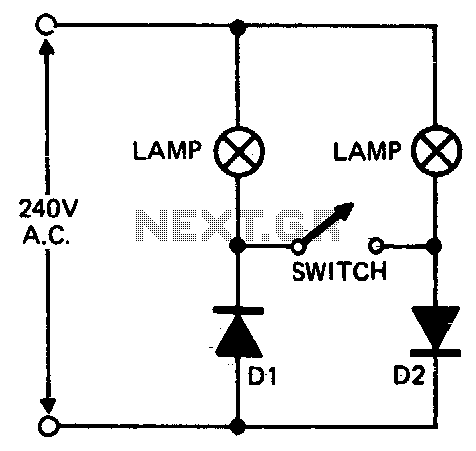
When setting up photographic floodlamps, it is sometimes desirable to operate the lamps at lower power levels until actually ready to take the photograph. The circuit allows the lamps to operate on half-cycle power when the switch is open...
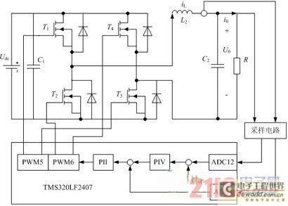
Traditional UPS systems use analog circuit control, which presents significant limitations for both manufacturers and users, regardless of whether they employ technology or SPWM technology. With advancements in information technology, the introduction of high-speed digital signal processing chips, known...
An amplifier to drive low to medium impedance headphones built using discrete components. Both halves of the circuit are identical. Both inputs have a DC path to ground via the input 47k control which should be a dual log...
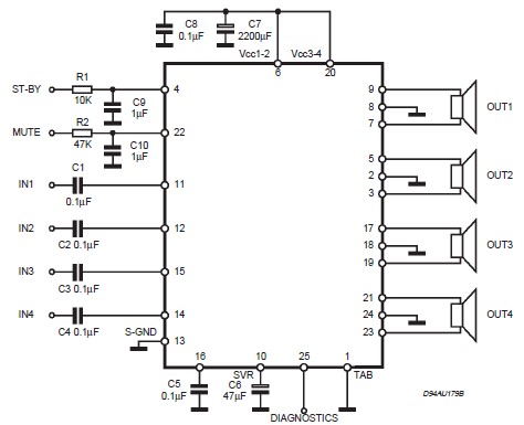
This circuit illustrates a car audio amplifier utilizing the TDA7381 integrated circuit (IC). The TDA7381 audio amplifier IC allows for the design of a straightforward 4x25 watts car radio. The TDA7381 is a high-performance audio amplifier designed specifically for automotive...
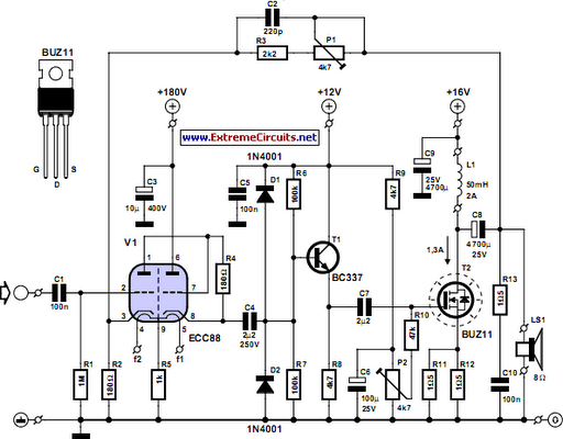
The ongoing debate regarding the superiority of valves versus transistors is not the focus here. However, for those uncertain about their choice, this simple amplifier serves as an excellent experiment. The design employs a valve as a pre-amplifier and...
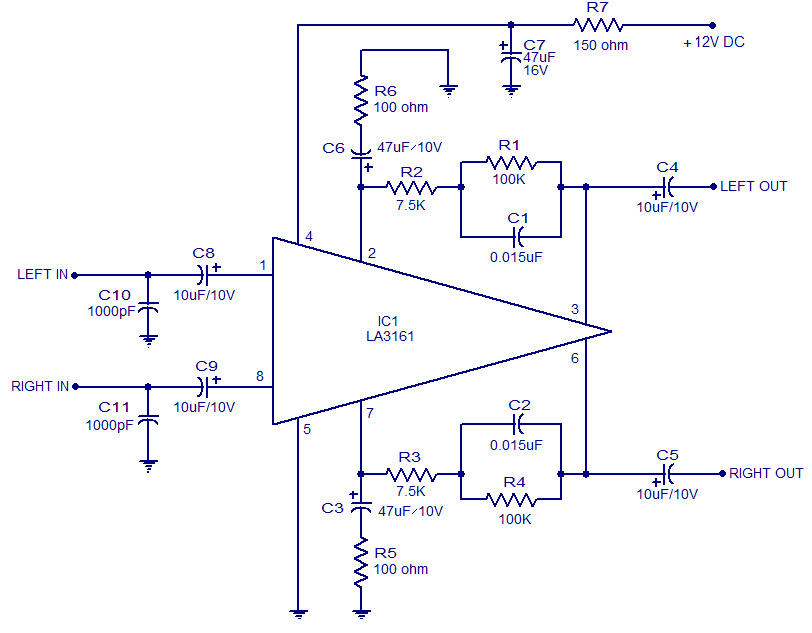
The LA3161 is an integrated two-channel preamplifier designed for car stereo applications. It operates on a 12V DC power supply. The LA3161 preamplifier is specifically engineered to enhance audio signals in automotive environments, ensuring optimal sound quality for car stereo...