
Car Audio Amplifier With TDA7381 IC

The TDA7381 is a high-performance audio amplifier designed specifically for automotive applications. It is capable of delivering 4 channels of output, each rated at 25 watts, making it suitable for driving speakers in a car audio system. The circuit typically includes power supply connections, input signal connections, and output connections to the speakers.
The power supply for the TDA7381 generally requires a voltage range of 8 to 18 volts, which is standard for automotive electrical systems. Adequate bypass capacitors should be placed near the power pins of the IC to ensure stable operation and minimize noise.
Input signals are usually fed into the amplifier through RCA connectors or directly from the head unit of the car audio system. The TDA7381 features built-in volume control and tone control, allowing for adjustments to sound quality and loudness directly from the amplifier circuit.
Output connections are made to four speakers, with the ability to drive both front and rear speakers in a vehicle. Proper speaker impedance matching is crucial, typically targeting 4 ohms for optimal performance and efficiency.
Additional components may include resistors and capacitors for filtering and stability, as well as heat sinks to dissipate heat generated by the amplifier during operation. The design should also consider the layout of the circuit board to minimize interference and maintain audio fidelity.
Overall, the TDA7381 car audio amplifier circuit provides an effective solution for enhancing the audio experience in vehicles, combining simplicity with robust performance.This circuit shows a car audio amplifier with TDA7381 IC. With the Tda7381 audio amplifier IC we can design a very simple 4x25 watts car radio .. 🔗 External reference
Related Circuits
The circuit comprises two main components: the Lisheng power amplifier and the rectifier filter section. The stereo audio power amplifier circuit diagram, depicted in Figure 5-85, illustrates only one channel, with the other channel being identical. The audio signal...
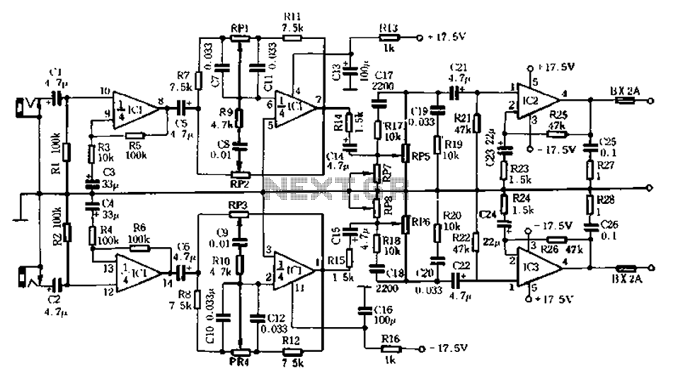
The circuit depicted in Figure 5-60 and Figure 6 utilizes an operational amplifier (op-amp) configured as a channel pre-amplifier to address the signal loss introduced by the tone control circuit. Additionally, another group of op-amps forms a channel-driven stage...
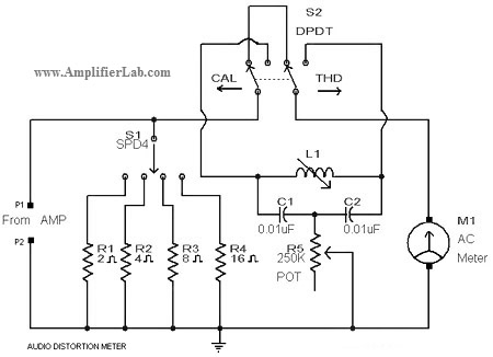
A circuit diagram of an audio distortion meter is presented here. An audio distortion meter is utilized to measure Total Harmonic Distortion (THD). The audio distortion meter is an essential tool in audio engineering, designed to quantify the level of...
The operating principle of the circuit is very simple. The first LED D1 is placed in series with the resistor R2 and diode D4. An only be lit this LED indicates that the battery is overcharged. For this reason,...
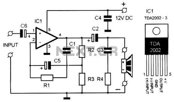
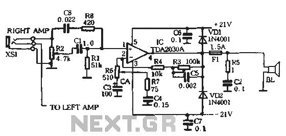
A compact, high-quality amplifier circuit that is also cost-effective. It utilizes the TDA2002, which provides very low distortion. The power supply should be between 12-15 volts at 1.2A. The amplifier's frequency response ranges from 40Hz to 15kHz. A suitable...
The circuit diagram presented is for a compact mini audio power amplifier that operates with a DC supply voltage ranging from 4.5 volts to a maximum of 18 volts. This amplifier utilizes the TDA1015 integrated circuit, produced by NXP...