
Simple Hybrid Audio Amplifier
This amplifier circuit is characterized by its unique hybrid design, combining the warmth of valve amplification with the efficiency of solid-state components. The ECC83 valve serves as the pre-amplifier, providing a rich harmonic content to the audio signal, while the MOSFET output stage ensures a robust performance with high current handling capabilities. The use of strong negative feedback not only enhances linearity but also minimizes distortion across the audio spectrum, making it suitable for high-fidelity applications.
The choice of components is critical in achieving the desired performance. The coupling capacitors (C1, C4, C7) should be of high quality to maintain signal integrity. MKT capacitors are adequate, but MKP types are preferred for their lower equivalent series resistance (ESR) and improved frequency response. The output stage's quiescent current, set by P2, is vital for Class A operation, ensuring that the MOSFET remains in its linear region, providing a smooth and distortion-free output.
The inductor L1 plays a significant role in the amplifier's low-frequency response. The original design's inductance of 150 mH, while higher than recommended, limits the amplifier's ability to reproduce bass frequencies effectively. A larger inductor with an iron core and air gap is essential for improved performance in the lower frequency range. The construction of such an inductor from E and I sections allows for a customized solution tailored to the amplifier's needs.
The power supply design is equally important, as it must deliver stable voltages while minimizing ripple to prevent hum. The cascade stage provides the necessary high voltage, while the dedicated voltage regulator ensures that fluctuations do not impact audio performance. The option to experiment with separate transformers for the filament supply allows for further optimization of the amplifier's performance.
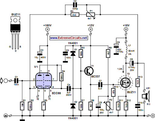
Overall, this amplifier design exemplifies the fusion of traditional valve technology with modern solid-state components, offering a platform for audio experimentation and enhancement while delivering quality sound reproduction.The debate still goes on as to which are better, valves or transistors. We don`t intend to get involved in that argument here. But if you can`t make your mind up, you should try out this simple amplifier. This amplifier uses a valve as a pre-amplifier and a MOSFET in the output stage. The strong negative feedback makes the frequency response as fl at as a pancake. In the prototype of the amplifier we`ve also tried a few alternative components. For example, the BUZ11 can be replaced by an IRFZ34N and an ECC83 can be used instead of the ECC88. In that case the anode voltage should be reduced slightly to 155 V. The ECC83 (or its US equivalent the 12AX7) requires 2 x 6. 3 V for the filament supply and there is no screen between the two triodes, normally connected to pin 9. This pin is now connected to the common of the two filaments. The filaments are connected to ground via R5. If you`re keeping an eye on the quality, you should at least use MKT types for coupling capacitors C1, C4 and C7.
Better still are MKP capacitors. For C8 you should have a look at Panasonic`s range of audio grade electrolytics. P1 is used to set the amount of negative feedback. The larger the negative feedback is, the flatter the frequency response will be, but the smaller the overall gain becomes. With P2 you can set the quiescent current through T2. We have chosen a fairly high current of 1. 3 A, making the output stage work in Class A mode. This does generate a relatively large amount of heat, so you should use a large heatsink for T2 with a thermal coefficient of 1 K/W or better.
For L1 we connected two secondary windings in series from a 2x18V/225 VA toroidal transformer. The resulting inductance of 150 mH was quite a bit more than the recommended 50 mH. However, with an output power of 1 W the amplifier had difficulty reproducing signals below 160 Hz. The distortion rose to as much as 9% for a signal of 20 Hz at 100 mW. To properly reproduce low-frequency signals the amplifier needs a much larger coil with an iron core and an air gap. This prevents the core from saturating when a large DC current flows through the coil. Such a core may be found in obsolete equipment, such as old video recorders. A suitable core consists of welded E and I sections. These transformers can be converted to the required inductor as follows: cut through the welding, remove the windings, add 250 to 300 windings of 0.
8 mm enamelled copper wire, firmly fix the E and I sections back together with a piece of paper in between as isolation. The concepts used in this circuit lend themselves very well to some experimentation. The number of supply voltages can be a bit of a problem to start with. For this reason we have designed a power supply especially for use with this amplifier (Quad power supply for hybrid amp).
This can of course just as easily be used with other amplifiers. The supply uses a cascade stage to output an unstabilised voltage of 170 V for the SRPP (single rail push pull) stage (V1). During initial measurements we found that the ripple on this supply was responsible for a severe hum at the output of the amplifier.
To get round this problem we designed a separate voltage regulator (High-voltage regulator with short circuit protection), which can cope with these high voltages. If you use a separate transformer for the filament supply you can try and see if the circuit works without R5.
During the testing we used a DC voltage for the filament supply. Although you may not suspect it from the test measurements (see table), this amplifier doesn`t sound bad. In fact, it is easily better than many consumer amplifiers. The output power is fairly limited, but is still enough to let your neighbours enjoy the music as well.
It is possible to make the amplifier more powerful, in which case we recommend that you use more than one MOSFET in the output stage. The inductor also needs to be made beefier. Since this is a Class A amplifier, the supply needs to be able to output the required current, which becomes much greater at higher output powers.
The efficiency of the amplifier is a bit over 30%. 🔗 External reference
Related Circuits
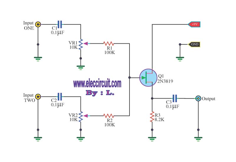
This circuit is a simple mixer circuit that can mix two signal channels into one output channel. It utilizes a codec circuit to convert stereo audio into mono audio. The circuit can also increase the number of channels by...
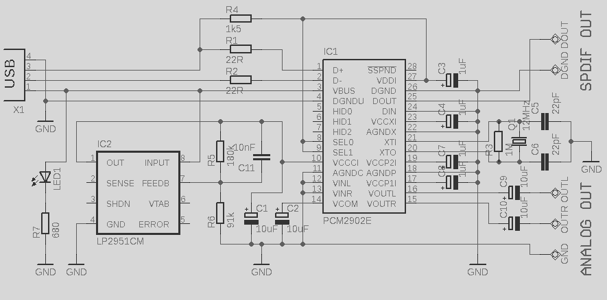
This circuit is a quality preamplifier with a built-in USB DAC designed for the Leachamp power amplifier. The schematic is based on the PCM2902 datasheet. The circuit includes a DAC and ADC, SPDIF input and output, and features three...

A Field Effect Transistor (FET) is an amplifying device where the output current is influenced by the input voltage. The FET preamplifier described here is sensitive. The Field Effect Transistor (FET) operates by utilizing an electric field to control the...
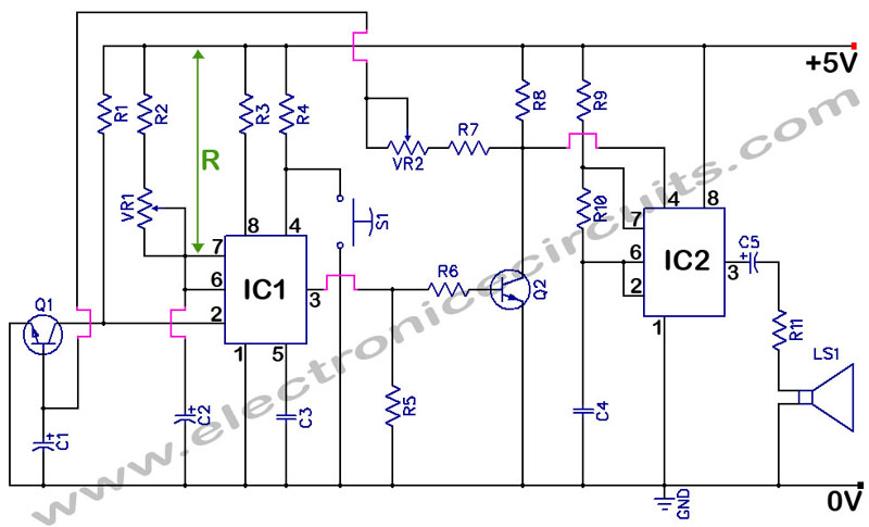
555 Timer with Audio Alarm Circuit. This circuit serves as a straightforward electronic timer equipped with an audio alarm feature. The 555 timer is a versatile integrated circuit widely used in various timer, delay, pulse generation, and oscillator applications. In...
This design is based on an 18 Watt Audio Amplifier and was developed primarily to address the needs of users who have difficulty locating the TLE2141C chip. It utilizes the commonly available NE5532 Dual IC; however, its power output...
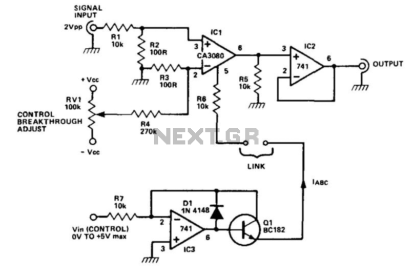
The CA3080 can be utilized as a gain-controlling device. The input signal is attenuated by resistors R1 and R2 so that a 20 mV peak-to-peak signal is applied to the input terminals. If this voltage exceeds a certain threshold,...