
50 watt power MOSFET amplifier circuit diagram

The described MOSFET-based power amplifier circuit is designed to efficiently amplify audio signals while maintaining high fidelity and low distortion. The operational range of +35V to -35V allows for significant headroom, making the circuit suitable for high-power applications.
At the input stage, the pre-filtering and pre-amplification processes are critical for ensuring that the signal fed into the MOSFET switch is clean and free from noise. The differential amplifier section, which employs a PNP transistor, serves to amplify the difference between two input signals, effectively enhancing the overall signal quality. This is particularly advantageous in audio applications where signal integrity is paramount.
The choice of MOSFETs, specifically the IRF9530 and IRF530, is essential for the amplifier's performance. These components are known for their high efficiency and capability to handle substantial power levels, making them ideal for use in a high-voltage differential amplifier configuration. The IRF9530 is a P-channel MOSFET, while the IRF530 is an N-channel MOSFET, allowing for complementary operation in the amplifier circuit.
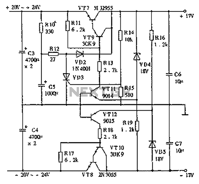
To implement this amplifier, a dual power supply circuit is necessary to provide the required positive and negative voltage rails. This dual supply configuration is crucial for the proper biasing of the MOSFETs and ensures that the amplifier can handle both the positive and negative cycles of the input audio signal without distortion.
In summary, this MOSFET power amplifier circuit is a sophisticated design that leverages a differential amplifier configuration to enhance audio signal quality. The use of high-performance MOSFETs and a dual power supply makes it suitable for demanding audio amplification tasks, ensuring reliable operation across its specified voltage range.This is a MOSFET transistor based power amplifier circuit that can be operated between +35V to -35V range. The input voltage is pre filtered and pre amplified before applying to the MOSFET switch. The pre audio amplifier is a differential amplifier section with PNP transistor. What is differential amplifier A difference amplifier is a type of powe r amp with two differential inputs which amplify the difference between two input signals. Here we are dealing with the circuit diagram and working of high voltage differential amplifier using IRF9530 and IRF530 MOSFET. You need a dual power supply circuit for this amplifier which I had posted earlier. 🔗 External reference
Related Circuits
China's national conditions indicate that the general living room area exceeds twenty square meters, often serving as a bedroom or listening room. For speakers with a sensitivity of 89 dB or higher, a pure Class A amplifier with a...
A circuit diagram for an animal repeller is provided. The circuit has been developed but is not functioning as intended. Assistance is requested for troubleshooting. The animal repeller circuit typically employs ultrasonic sound waves to deter animals from specific areas....
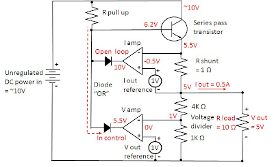
Most power supplies regulate either their output voltage or current at a constant level, depending on the load resistance relative to the power supply's output voltage and current settings. This can be summarized as follows: To accomplish this, most...
The TDA2030 is capable of delivering 20 watts of audio power; however, the output has been intentionally reduced to approximately 8 watts to drive 10-watt speakers, which is sufficient for smaller rooms. The input sensitivity is 200mV, and higher...

This circuit has a long history, originating from an idea by Rich Piotter and later refined by Wilf Rigter and Bruce Robinson. The final result does not include the necessary motor drivers, which are typically H-bridge based, but presents...
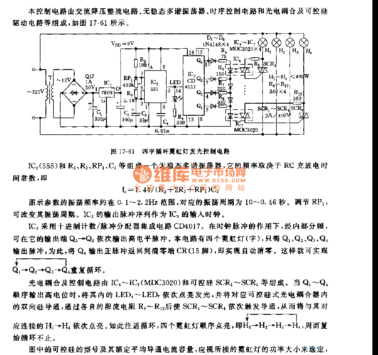
This control circuit consists of an AC step-down rectifier circuit, an astable multivibrator, a timing control circuit, an optocoupler circuit, and an SCR driving circuit, as illustrated in Figure 17-61. The astable multivibrator is formed using IC2 (555), resistors...