
5-motor hexapod circuit

This circuit represents a collaborative evolution of design ideas within the community, reflecting iterative enhancements that improve functionality and usability. The initial concept by Rich Piotter laid the groundwork for a circuit intended for robotic applications, particularly in the domain of BEAM robotics, which emphasizes minimalistic and efficient designs.
Wilf Rigter's contribution focused on refining the circuit to enhance its performance, likely addressing issues such as component count and overall complexity. The simplification process by Bruce Robinson further streamlined the design, making it more accessible for hobbyists and engineers alike. The reduction in pin count suggests a move towards a more compact and efficient circuit layout, which is crucial in applications where space and power efficiency are paramount.
Although the final schematic does not depict the motor drivers, it is essential to consider that H-bridge configurations are typically employed in such circuits to control the direction and speed of motors. An H-bridge allows for bidirectional control of a motor, enabling it to rotate in both clockwise and counterclockwise directions, which is particularly useful in robotic applications where maneuverability is required.
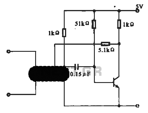
The announcement by "Sparky" Garvin served to disseminate this innovative design within the community, highlighting the importance of collaboration and shared knowledge in the field of electronics. The cumulative efforts of these engineers illustrate the iterative nature of circuit design, where each version builds upon the last, leading to more refined and effective solutions for practical applications. This circuit's legacy continues to inspire new designs and improvements in the realm of robotics and beyond.This circuit has a long and storied history - starting with an idea by Rich Piotter, then being honed and simplified by Wilf Rigter and Bruce Robinson. The final result does not show the necessary motor drivers (usually H-bridge based), but here`s the high-level circuit: Rich started this off with a circuit he posted to the Yahoo BEAM group on 9/
25/2000 in post #5955. A few days later, Wilf presented his version of the circuit in Yahoo groups post #6020. Over the course of the next year, Bruce simplified things a bit, reducing pin count, yielding the circuit diagram above. This final version was unleashed upon the world indirectly, via an announcement by "Sparky" Garvin in Yahoo groups post #19029.
🔗 External reference
Related Circuits
All car batteries require a 12V battery charger, which also applies to marine, RV, and power sports batteries. The high-efficiency lead-acid batteries available today necessitate more effective charging techniques. The battery charger is a crucial tool for prolonging battery...
The digital thermometer consists of a temperature sensor, a single stabilizing circuit, a counter circuit, a decoding section, a driving circuit, and LED digital tubes among other components. It operates within a temperature range of 0 to 50 degrees...
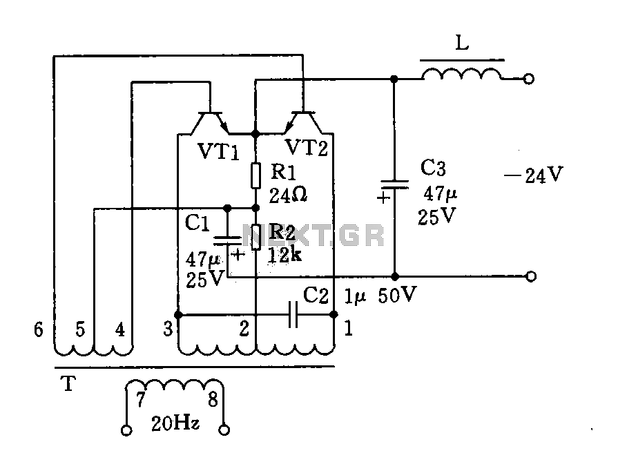
The circuit described is a 20Hz signal generator suitable for telephone ringing systems, alarm systems, and various other electronic applications. It consists of a transformer (T) and two transistors (VT1 and VT2), forming a push-pull oscillator. The two transistors...
This precise one-pulse-per-second clock is constructed using a few common components and is driven by a 50 or 60 Hertz mains supply without any direct connection to it. A beep or a metronome-like click, along with a visible flash,...

The following circuit illustrates a Bedside Lamp Timer Circuit Diagram. This circuit is based on the CD4060 integrated circuit. Features: An LED illuminates for approximately 25 seconds. The Bedside Lamp Timer Circuit utilizes the CD4060 IC, which is a versatile...
This circuit illustrates an oscillator that is controlled by an optocoupler, utilizing photoelectric coupling to drive a transistor. The oscillator circuit described operates by employing an optocoupler to provide electrical isolation between its input and output stages while allowing control...