
how does power supply regulate its

If the load is increased by reducing the output load resistance from 10 ohms to 3 ohms, the circuit diagram of the basic 5-volt, 1-amp output series regulated power supply is revised for operation in Constant Current mode with a 3-ohm load resistor. Since the load resistor is lower than (V_out / I_out) = 5 ohms, the power supply switches to CC mode. The CC error amplifier takes control when the voltage drop across the current shunt resistor increases to match the 1-volt reference value, corresponding to a 1-amp output, drawing excess base current from the series pass transistor through the diode OR network. The CC amplifier now operates in closed loop, regulating the output current to maintain its input error voltage at zero. Meanwhile, the actual output voltage drops to 3 volts, and the CV amplifier attempts to increase the output voltage but cannot because the CC amplifier has control of the output. The CV amplifier operates in open loop, with its output reaching its positive limit while exhibiting -0.4 volts of error voltage. The output I-V diagram for this Constant Current operation is also illustrated.
Power supplies typically incorporate separate current and voltage control loops to regulate their outputs in either Constant Voltage (CV) or Constant Current (CC) mode. The control mode is determined by the relationship between the load resistance and the power supply's output voltage and current settings. This design ensures the protection of both the load and power supply by limiting the voltage and current delivered to the load.
The schematic for a series regulated power supply consists of several key components: a transformer to step down the input voltage, a rectifier to convert AC to DC, and a filter capacitor to smooth the output voltage. The CV and CC control loops are implemented using operational amplifiers (op-amps) configured to monitor the output voltage and current. A resistor divider network is used for voltage feedback, while a shunt resistor is employed for current sensing. The series pass transistor, typically a bipolar junction transistor (BJT) or a MOSFET, acts as the controllable element that adjusts the output based on feedback from the control loops. The diode OR network facilitates the sharing of control between the CV and CC amplifiers, ensuring that only one loop is active at any given time, thus providing stable and reliable power supply operation.Most all power supplies regulate either their output voltage or output current at a constant level, depending on the load resistance relative to the power supply`s output voltage and current settings. This can be summarized as follows: To accomplish this most all power supplies have separate voltage and current feedback control loops to limit either the output
voltage or current, depending on the load. To illustrate this Figure 1 shows a circuit diagram of a basic 5 volt, 1 amp output series regulated power supply operating in CV mode. The CV and CC control loops/amplifiers each have a reference input value. In this case the reference values are both 1 volt. In order to regulate output voltage the CV error amplifier compares its 1 volt reference against a resistor divider that divides the output voltage down by a factor of 5, limiting the output voltage to 5 volts.
Likewise the CC error amplifier compares its 1 volt reference against a 1 ohm current shunt resistor located in the output current path, limiting the output current to 1 amp. For Figure 1 the load resistance is 10 ohms. Because this load resistance is greater than (V out / I out) = 5 ohms, the power supply is operating in CV mode.
The CV error amplifier takes control of the series pass transistor by drawing away excess base current from the series pass transistor, though the diode OR network. The CV amplifier is operating in closed loop, maintaining its error voltage at zero volts. In comparison, because the actual output current is only 0. 5 amps the CC amplifier tries to turn the current on harder but cannot because the CV amplifier has control of the output.
The CC amplifier is operating open loop. Its output goes up to its positive limit while it has -0. 5 volts of error voltage. The output I-V diagram for this Constant Voltage operation is shown in Figure 2. Now say we increase the load by lowering the output load resistance from 10 ohms down to 3 ohms. Figure 3 shows the circuit diagram of our basic 5 volt, 1 amp output series regulated power supply revised for operating in CC mode with a 3 ohm load resistor. Because the load resistor is lower than (V out / I out) = 5 ohms, the power supply switches to CC mode.
The CC error amplifier takes control when the voltage drop on the current shunt resistor increases to match the 1 volt reference value, corresponding to 1 amp output, drawing excess base current from the series pass transistor though the diode OR network. The CC amplifier is now operating closed loop, regulating the output current to maintain its input error voltage at zero.
In comparison, because the actual output voltage is now only 3 volts the CV amplifier tries to increase the output voltage but cannot because the CC amplifier has control of the output. The CV amplifier is operating open loop. Its output now goes up to its positive limit while it has -0. 4 volts of error voltage. The output I-V diagram for this Constant Current operation is shown in Figure 4. As we have seen most all power supplies have separate current and voltage control loops to regulate their outputs in either a Constant Voltage (CV) or in a Constant Current (CC) mode.
One or the other takes control, depending on that the load resistance is in relation to what the power supply`s output voltage and current settings are. In this way both the load and power supply are protected by limiting the voltage and current that is delivered by the power supply to the load.
By 🔗 External reference
Related Circuits
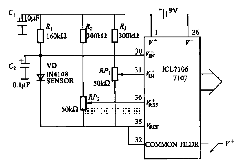
A diode temperature sensor is utilized in a 3-digit thermometer, featuring a 3-digit A/D converter and display driver IC L7106/7107. This configuration amplifies the signal, performs A/D conversion, and executes a series of decoding and display driver processes to...
The LED flasher circuits below operate on a single 1.5 volt battery. The circuit on the upper right uses the popular LM3909 LED flasher IC and requires only a timing capacitor and LED. The top left circuit, designed by...
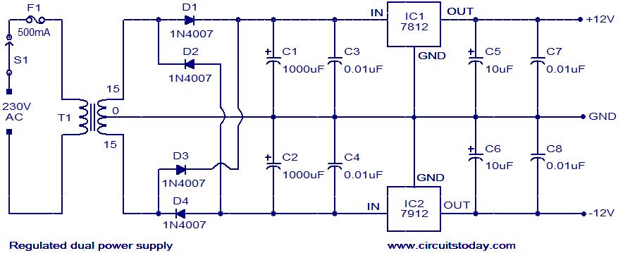
The circuit described is a regulated dual power supply that provides +12V and -12V from the AC mains. Such a power supply is an essential tool for electronic hobbyists. The transformer T1 reduces the AC mains voltage, while diodes...

This application note discusses the use of SEPIC power modules to supply the necessary power for driving high-brightness LED arrays. These arrays serve as display backlights and necessitate a wide dimming range. The SEPIC configuration offers an efficient and...
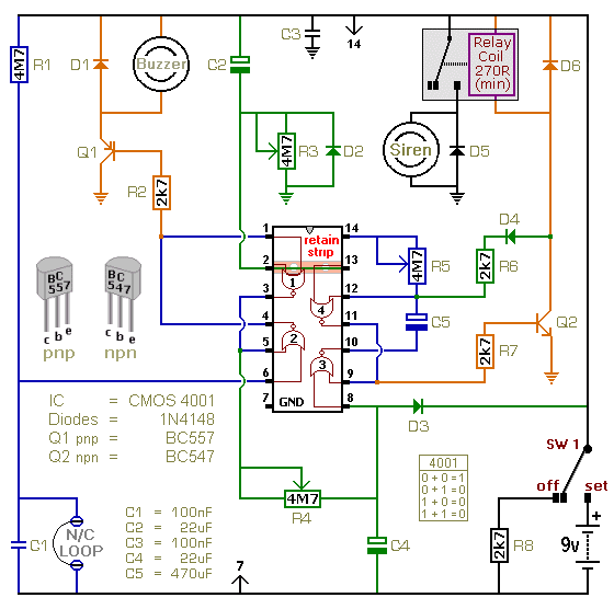
This is a single-zone alarm system featuring independently adjustable Exit, Entry, and Siren Cut-Off timers. It is designed to accommodate standard normally-closed input devices, such as magnetic reed contacts, foil tape, and passive infrared sensors (PIRs). The system can...
Electronic schematics collections provide a platform for discussions related to electronic circuit schematics, printed circuit board (PCB) diagrams, and various electronics projects. These collections serve as valuable resources for engineers, students, and hobbyists interested in electronics design and development. They...