
5000 Volts arc supply
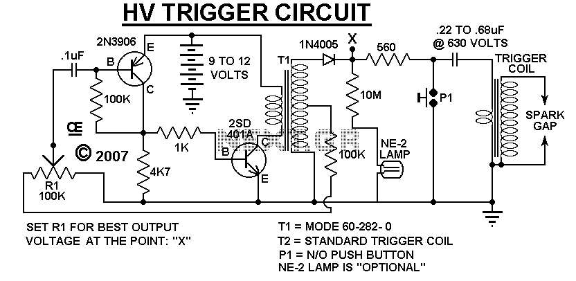
The described circuit operates as a manually triggered high-voltage spark generator, capable of producing peak output voltages exceeding 5,000 volts. The primary components include an audio transformer (T1) and a trigger coil (T2), which are critical for the voltage step-up and discharge process.
T1, the audio transformer, is responsible for stepping up the input voltage to approximately 500 volts at point X in the schematic. This transformer is typically compact and designed for low current applications, making it suitable for generating the necessary voltage levels without excessive power consumption. The high-voltage output from T1 is essential for initiating the spark generation process.
The second component, T2, serves as the trigger coil, which can either be a standard trigger coil commonly found in strobe kits or a custom-wound coil similar to those utilized in stun gun designs. The choice of T2 is crucial, as it determines the circuit's overall performance and reliability. A standard trigger coil may provide adequate performance for basic applications; however, a custom coil can be tailored to optimize the spark generation characteristics.
It is important to note that excessive arcing can lead to internal arcing within T2, resulting in permanent damage and short-circuiting the coil. To prevent this, it is advised to start with a small arc and gradually increase the distance until the maximum arc length is achieved. Once the maximum distance is found, it is prudent to reduce the arc length slightly to ensure a safety margin, thereby preventing potential damage to the components.
Overall, this circuit design emphasizes careful handling and gradual adjustments to achieve high voltage spark generation, while minimizing the risk of component failure. Proper understanding and implementation of the described components and operational guidelines will enable effective use of this high-voltage spark generator.A Very Low Current, High Voltage Spark, that is "Manually Triggered". Although its not easily Measured, the Peak Ouput voltage will be over 5,000 Volts. T1 is a small audio transformer and it steps up the voltage to about 500 Volts at Point "X" on the schematic. The main power limitation to this device is T2. It can be a Standard Trigger Coil, like those used on Strobe Kits, or a Custom made Trigger Coil. For A Custom coil, You can wind one Simular to those in my Stun Gun Write-ups. Which-Ever Coil you use for T2, If you try for Too long of an Arc, It will Arc Internally, Permanently Shorting itself Out.
So Start with a Small Arc and Slowly Increase it to try and find the Maximum Distance. Than Reduce it Slightly to give a small Safety Margin. 🔗 External reference
Related Circuits
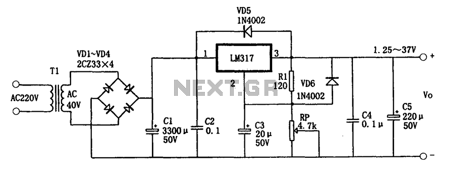
The adjustable power supply circuitry operates within a voltage range of 1.25 to 37V. It utilizes a three-terminal regulator, which is known for its good performance and stability. The compact size of the design facilitates easy installation, and it...
High-voltage power supply circuit for fluorescent light power supply. Refer to that page for an explanation of the related circuit diagram. The high-voltage power supply circuit designed for fluorescent lights typically consists of several key components that work together to...
The ratio R1/R2 determines the amplitude of the triangle wave in relation to the square-wave output. The frequency of oscillation for both waveforms can be calculated using the equation: fo = 1/(4R3C1) * (R2/R1). In this circuit, R1 and R2...
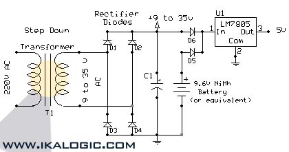
This circuit supplies electric power from a backup battery when AC power is interrupted, ensuring a stable 5V power supply for sensitive devices such as microcontrollers and logic circuits. The capacitor C1 should have a capacitance greater than 220...
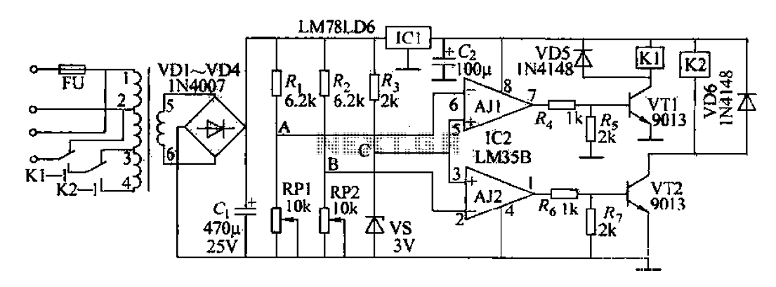
The AC power supply circuit primarily consists of a power supply, a reference voltage, a voltage comparator for sampling, and several other components. It includes a transformer for the input, an autotransformer tap for the control power supply circuit,...
These power supply circuits generate 500 volts, but they can be modified to supply several hundred to nearly 1000 volts by changing the zener diodes. These circuits produce high voltages and can cause dangerous shocks. Caution is advised; these...