
1.25 ~ 37V LM317 adjustable power supply configuration
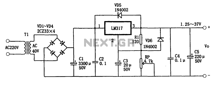
The adjustable power supply circuit described utilizes the LM317 voltage regulator, which is a popular choice for providing stable output voltages in various applications. The circuit is designed to allow users to adjust the output voltage within a specified range, making it versatile for different experimental setups.
The three-terminal design of the LM317 simplifies the integration of the regulator into various circuits, providing a straightforward means of adjusting voltage levels. The output voltage is determined by the resistors R2 and Rp, which form a voltage divider. The formula for output voltage indicates that by varying the resistance values, the output can be fine-tuned to meet specific requirements.
The inclusion of capacitors C3 and C4 plays a critical role in maintaining the stability of the power supply. C3 filters out any high-frequency noise or ripple that may be present in the output, ensuring a clean and stable voltage is delivered to the load. C4 prevents potential oscillations that could arise from feedback in the circuit, thus protecting the integrity of the output voltage.
Diodes VD5 and VD6 provide essential protection mechanisms for the LM317. VD5 safeguards against back-emf and voltage spikes that could occur during capacitive load discharges, while VD6 ensures that any excess charge from C2 is safely diverted, preventing damage to the LM317 regulator.
Overall, this adjustable power supply circuit is well-suited for experimental applications, offering a reliable and stable source of power with adjustable voltage levels and built-in protection features. Its compact design and ease of installation make it an excellent choice for various electronic projects.1.25 ~ 37V as shown for the adjustable power supply circuitry. It is adjustable three-terminal regulator typical application circuit, characterized by good performance, stable, small size, making installation easy, the maximum output current of l.5A, the output voltage between 1.25 ~ 37V continuously adjustable. It is best suited to experiment with power.FIG C3 for filtering out the ripple on the RP, improve the stability of power supply output voltage.
For some reason when the output terminal and the input of LM317 short, C2 will discharge through internal damage LM317 chip, VD6 provides for the discharge circuit C2. C4 is used to prevent the output of self-excitation. VD5 as protection diodes to prevent the accumulation of short-circuit on the input of the capacitive load charge to the LM317 discharge.
In order to ensure reliable operation LM317. Rl resistance and generally 120 (or 240 ). Expression of the output voltage Vo: Vo 1.25 (1 + R2/Rp) V.
Related Circuits
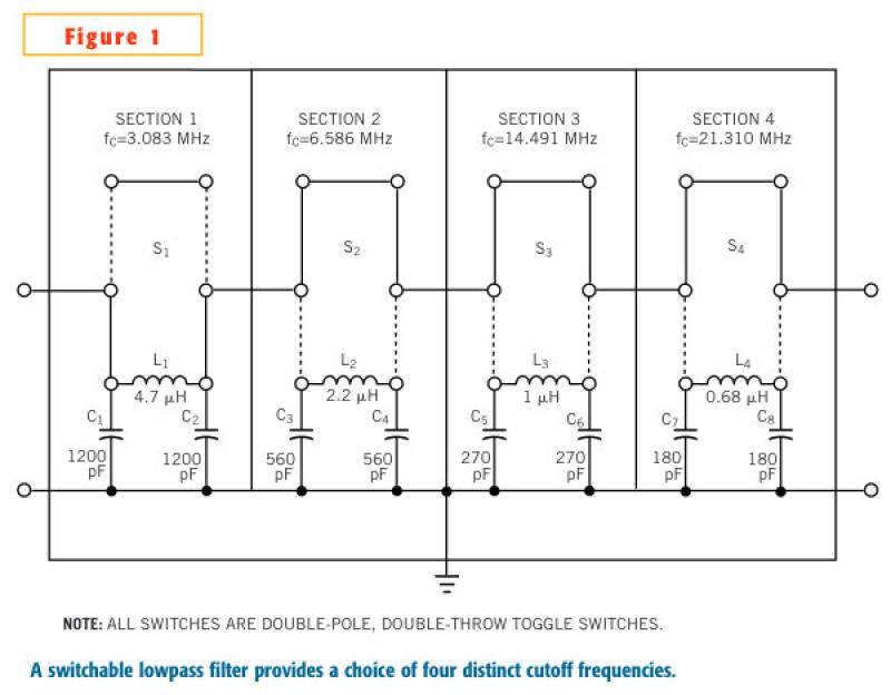
In an adjustable lowpass filter, each filter section uses commonly available components. This example uses filter-section cutoff frequencies for standard inductors and capacitors without the need for any extra components in series or parallel. Fixed inductors are Coilcraft 90...
I had designed up an oscillator with a Power Output circuit. Problem was when power was applied to the entire circuit, the output of the Oscillator gave a Momentary Spike into the output circuit. Thus Driving it full on...
LEDs are great display tools. Their prices have decreased to a point where they are replacing more conventional light sources. In one sense, their characteristic need for low voltages is an advantage, e.g., compatibility with I.C. drives, but this...
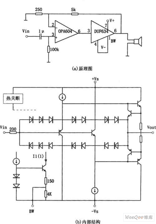
The provided image depicts a high-performance and low-power audio power amplifier circuit. The initial stage utilizes the MOSFET hi-fi operational amplifier OPA604, while the subsequent stage employs the high-speed buffer BUF634. Voltage series negative feedback is implemented between the...
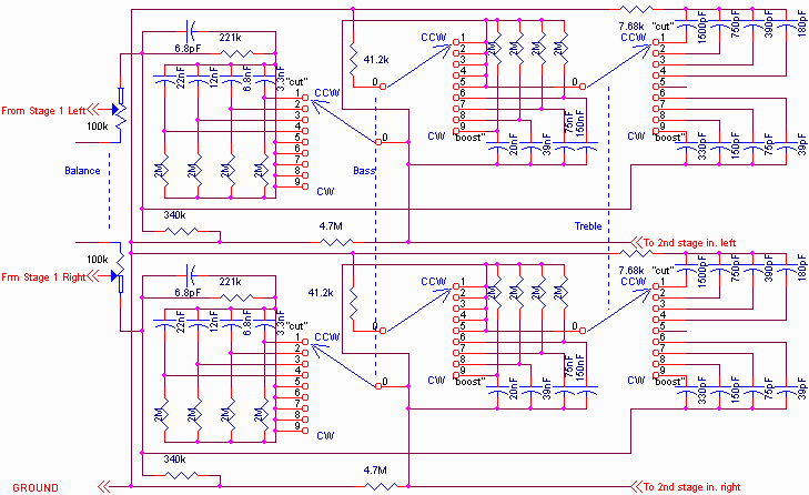
The primary amplifying stages consist of triode-connected 6088 tubes. As previously mentioned, there are two amplifying stages, which provide a non-inverted input to output connection and sufficient gain to include tone control. The tone controls are switch-selected, allowing a...
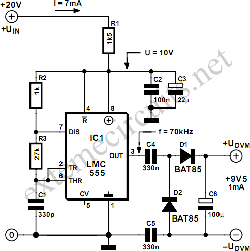
Most commercial digital voltmeter (DVM) modules with an LCD readout are powered by 9 volts and utilize an ICL7106 or similar analog-to-digital (A-D) converter chip. These modules are commonly employed in laboratory power supplies and other test and measurement...