
5000W ultra-light high-power amplifier without switching-mode power supply
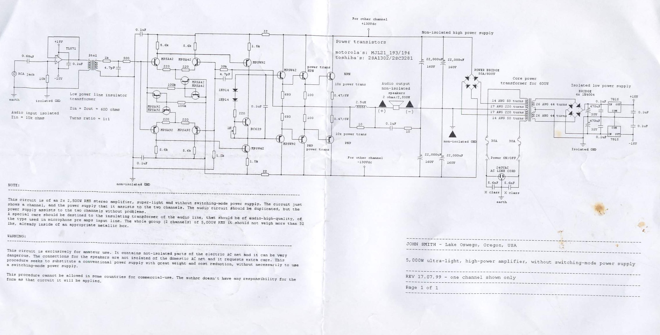
This circuit design features a dual-channel amplifier capable of delivering 2x 500W RMS output. The architecture is lightweight, making it suitable for portable applications, and it intentionally avoids the complexities and weight associated with traditional switching-mode power supplies. The schematic primarily illustrates one channel, with the understanding that a second identical circuit is to be replicated for stereo functionality. The power supply is engineered to efficiently support both channels, ensuring reliable performance.
Critical to the circuit's operation is the selection of a high-quality insulating transformer. This component is essential for maintaining audio fidelity and minimizing noise, particularly in sensitive audio applications like microphone preamps. The transformer should be rated for audio applications to ensure optimal performance.
The combined power output of the amplifier is rated at 5,000W RMS, making it suitable for various amateur audio setups, such as home theaters or live sound reinforcement. The design emphasizes portability, with the entire assembly, including the power supply and amplifier circuits, weighing no more than 32 lbs when enclosed in a robust metallic chassis. This weight consideration is crucial for users who may need to transport the amplifier frequently.
Safety is a paramount concern in this design. The circuit contains components that are not isolated from the AC mains, which introduces risks of electric shock. Users must exercise caution when handling the device, particularly when connecting speakers, as these connections are also not isolated from the domestic AC network. It is imperative to implement safety measures to mitigate these risks, especially in amateur applications where users may lack extensive electrical knowledge.
This circuit represents an innovative approach to audio amplification, prioritizing weight and cost efficiency while maintaining performance. However, it is essential to note that the design may not comply with commercial regulations in certain jurisdictions, and users must assume responsibility for the application of this circuit.This circuit is of an 2x 2, 500W RMS stereo amplifier, super-light and without switching-mode power supply. The circuit just shows a channel, and the power supply that it assists to the two channels. The audio circuit should be duplicated, but the power supply assists to the two channels without problems.
A special care should be destined to the in sulating transformer of the audio line, that should be of audio-high-quality, of the type used in microphone pre amps input line. The whole group (2 channels) of 5, 000W RMS it should not weigh more than 32 lbs, already inside of an appropriate metallic box.
This circuit is exclusively for amateur use. It contains not-isolated parts of the electric AC net and it can be very dangerous. The connections for the speakers are not isolated of the domestic AC net and it requests extra care. This procedure seeks to substitute a conventional power supply with great weight and cost reduction, without necessarily to use a switching-mode power supply. This procedure cannot be allowed in some countries for commercial-use. The author doesn`t have any responsibility for the form as that circuit it will be applied. 🔗 External reference
Related Circuits
This is an aerial current power supply with a continuously adjustable stabilized output ranging from 0 to 30VDC. The circuit also incorporates an electronic current limiter that effectively controls the output current from a few milliamperes (2 mA) to...
What value of potentiometer should be used for the volume control of this audio amplifier circuit, and where should it be connected? Thank you. In audio amplifier circuits, the choice of potentiometer value for volume control is crucial for achieving...
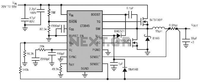
Burst Mode operation maintains high efficiency at light loads by reducing IC quiescent current to 120 µA. Light load efficiency is also improved with the reverse inductor current inhibit function, which supports discontinuous operation. Additional features include an adjustable...
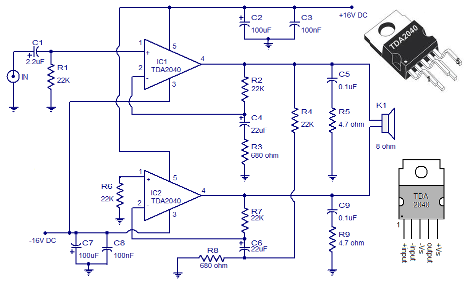
A 30 Watt audio amplifier circuit utilizing the TDA2040 is illustrated here. The TDA2040 is a class AB monolithic integrated audio amplifier available in a Pentawatt package. This integrated circuit features low harmonic distortion, minimal crossover distortion, and includes...
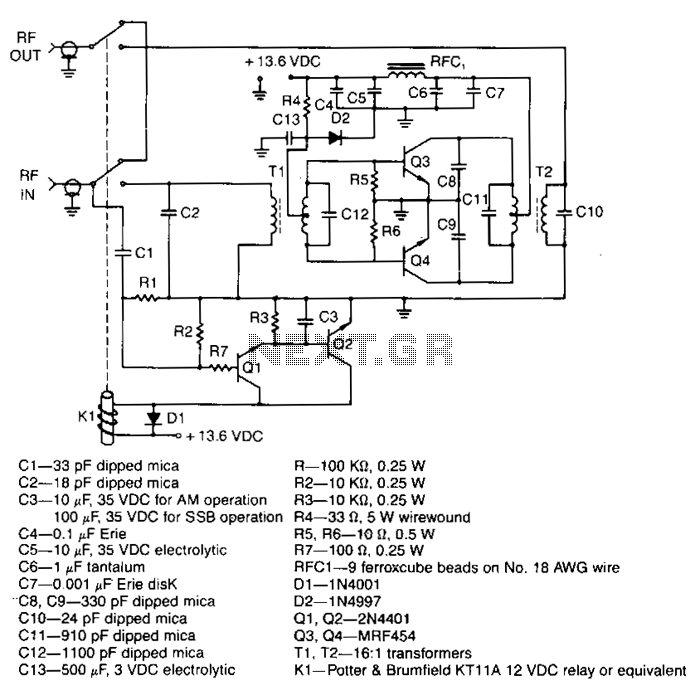
This amplifier delivers a nominal output power of 140 watts peak envelope power (PEP) when fed with input levels as low as 3 watts. Both the input and output transformers feature a 4:1 turn ratio and a 16:1 impedance...
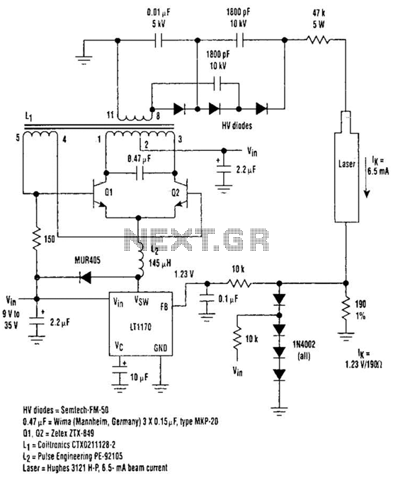
Driving Helium-Neon lasers can be greatly simplified using this power supply configuration. When power is applied, the laser does not conduct, and the voltage across the 190-ohm resistor is zero. However, a resonant circuit and a voltage tripler then...
Warning: include(partials/cookie-banner.php): Failed to open stream: Permission denied in /var/www/html/nextgr/view-circuit.php on line 713
Warning: include(): Failed opening 'partials/cookie-banner.php' for inclusion (include_path='.:/usr/share/php') in /var/www/html/nextgr/view-circuit.php on line 713