
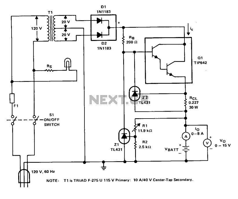
STABILIZER POWER SUPPLY 0-30 VDC CIRCUIT
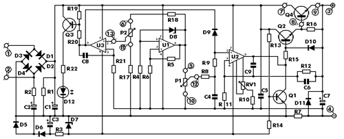
The described power supply circuit is designed to provide a stable voltage output that can be finely tuned according to the needs of various electronic experiments. The adjustable voltage output is achieved through the use of a voltage regulator circuit, which can include components such as operational amplifiers, transistors, or integrated voltage regulator ICs. This allows the user to set the desired output voltage within the specified range of 0 to 30VDC.
The electronic current limiter is a crucial feature that prevents excessive current from damaging sensitive components in experimental setups. This is typically accomplished using a feedback mechanism that monitors the output current. If the current exceeds a predetermined threshold, the circuit reduces the output voltage, thereby limiting the current to the set maximum of three amperes. This can be implemented using a combination of resistors, transistors, and operational amplifiers to create a feedback loop that dynamically adjusts the output based on the load conditions.
Visual indication of the current limiting operation can be achieved using an LED or another type of indicator light. This indicator is connected to the output of the current sensing circuit, illuminating when the current limiter is actively engaged. This feature enhances usability by providing immediate feedback to the user regarding the operational status of the power supply.
Overall, this power supply circuit is not only versatile in its output capabilities but also emphasizes safety and reliability, making it an invaluable tool for engineers and hobbyists involved in electronic experimentation.This is a aerial affection ability accumulation with a continuously capricious stabilised achievement adjustable at any amount amid 0 and 30VDC. The ambit additionally incorporates an cyberbanking achievement accepted limiter that finer controls the achievement accepted from a few milliamperes (2 mA) to the best achievement of three amperes that t
he ambit can deliver. This affection makes this ability accumulation basal in the experimenters class as it is accessible to absolute the accepted to the archetypal best that a ambit beneath analysis may require, and ability it up then, after any abhorrence that it may be damaged if article goes wrong. There is additionally a beheld adumbration that the accepted limiter is in operation so that you can see at a glance that your ambit is beyond or not its preset limits.
🔗 External reference
Related Circuits
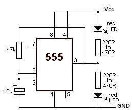
This LED flasher circuit utilizes a 555 timer integrated circuit (IC). The circuit diagram is straightforward and requires only a few external components. When operational, the red LEDs will flash sequentially at a predetermined frequency, similar to the indicators...
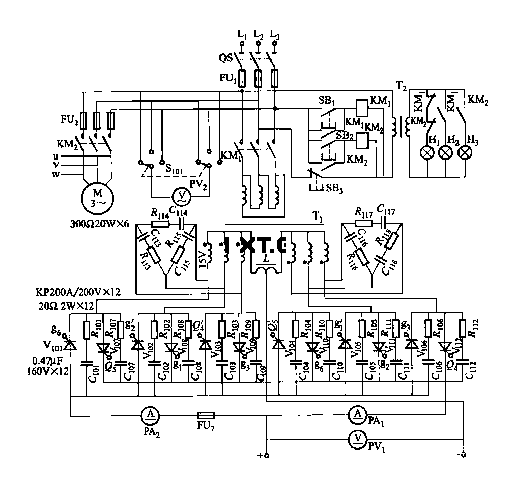
FGDF-3 is a three-phase low-temperature iron plating main circuit, while the KGDF-3 represents a low-temperature iron plating power supply device that includes characteristics of a single-phase low-temperature iron plating power supply. This device utilizes a three-phase power grid to...
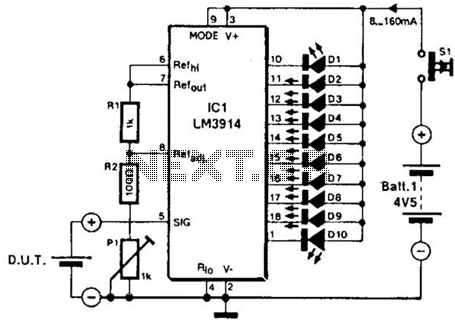
The LM3914A bar graph LED is utilized as a voltmeter for testing batteries. This circuit operates on a 4.5-V battery and compares the battery under test with an internally generated reference, established by resistors R1, R2, and potentiometer P1....
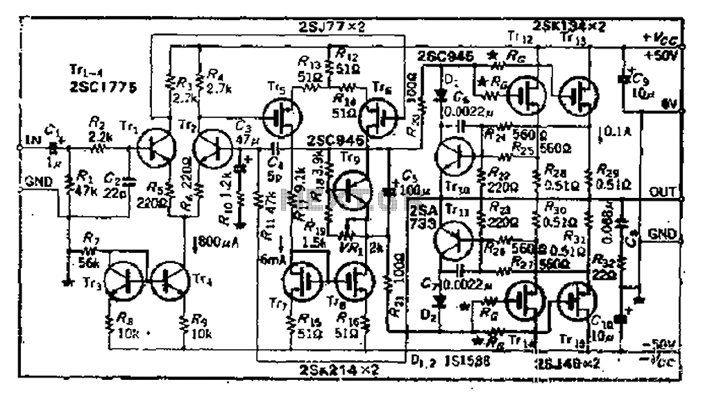
The circuit consists of three identical basic stages, with the second stage featuring a differential output from the power MOSFET, 2SJ77. A current mirror circuit utilizing 2SK214 is implemented. The operating current is 6mA; however, due to the power...
The charger operates with a charging voltage of 2.4 V per cell, aligning with the recommendations of most manufacturers. The circuit delivers a charging voltage of 14.4 V (6 cells at 2.4 V per cell) in a pulsed manner...
This sound level meter circuit can be used to control the intensity of a sound recording or in a disco. It has 5 measurement domains between 70 and 120 dB. The sound level meter circuit is designed to measure sound...