
500kHz to 4 MHz Converter
The final tuned circuit resonates near 3.7 MHz. Again, an unknown number of turns on an unknown toroid was used. However, a toroid such as the 9 mm and 13 mm purple Philips types should work adequately in this part of the circuit. The purist may want this circuit to be resonant at the receiver's exact frequency; this can be arranged by making the 100 pF capacitor variable.
In Australia, the main signals below 500 kHz are LF Aircraft beacons. Details of these are provided in the Australian Amateur Callbook. If VK amateurs succeed in obtaining a LF allocation, the converter could be a starting point towards a full transverter for these frequencies.
This converter circuit is designed to extend the frequency reception capabilities of standard HF receivers, particularly those that lack sensitivity or tuning capability in the lower frequency bands below 500 kHz. The core of the design employs the NE602 integrated circuit, which functions as both a mixer and an oscillator. This dual functionality allows for the mixing of incoming signals with a local oscillator frequency derived from a 4 MHz crystal, effectively translating lower frequencies into a range that the HF receiver can process.
The tuning mechanism is unique in that it operates in reverse for certain frequency ranges. When tuning to a lower frequency signal, the user will find that a setting of 100 kHz on the tuning dial corresponds to an output frequency of 3.9 MHz, while 500 kHz corresponds to 3.5 MHz. This is particularly beneficial for users who have receivers capable of tuning above 4 MHz, as it allows for straightforward tuning into the 4 to 4.5 MHz range for better clarity and identification of unknown signals.
The low pass filter preceding the mixer is critical in preventing interference from strong local broadcasts, ensuring that only the desired signals are processed. The inductance for this filter can be adjusted, with recommendations suggesting a starting point between 10 and 50 µH. Experimentation with the filter design may be necessary, particularly for users located near powerful broadcast stations, who may benefit from a multi-section filter design to enhance selectivity.
The resonant circuit, which is designed to resonate around 3.7 MHz, can be fine-tuned using a variable capacitor, allowing users to match the circuit's resonance to their specific receiver frequency. The choice of ferrite toroid for the inductors is flexible, with common options being the purple Philips types, which are readily available.
For amateur radio enthusiasts in Australia, this converter opens up the possibility of receiving LF aircraft beacons and could serve as a foundational component for developing a more comprehensive transverter system for lower frequency allocations, should they become available. The circuit's design emphasizes simplicity and adaptability, making it an accessible project for those interested in expanding their radio receiving capabilities.This converter allows reception of signals below 500 kHz on a 3.5 ? 4 MHz HF receiver. It should therefore be useful for those with receivers that do not receive the lower frequencies. Again the converter uses the popular NE602 mixer/oscillator chip. A cheap 4 MHz crystal provides the local oscillator tuning. Note that tuning is backwards ? 100 kHz corresponds with 3.9 MHz and 500 kHz with 3.5 MHz. If your receiver tunes above 4 MHz, the 4 ? 4.5 MHz range will provide forwards tuning, making it easier to ascertain the frequency of an unknown station. The mixer is preceded by a low pass filter to attenuate strong local broadcast stations above 500 kHz.
An unknown number of turns on an unknown ferrite toroid was used for this filter. As a starting point, I would suggest an inductance of between 10 and 50 uH. Build the converter first and then experiment with the filter if it is found necessary. Those very near broadcast stations may use two or three sections instead of the single section used here. The final tuned circuit resonates near 3.7 MHz. Again an unknown number of turns on an unknown toroid was used. However a toroid such as the 9mm and 13mm purple Philips types should work OK in this part of the circuit.
The purist may want this circuit to be resonant at the receiver's exact frequency ? this can be arranged by making the 100pF capacitor variable. In Australia the main signals below 500 kHz are LF Aircraft beacons. Details of these are provided in the Australian Amateur Callbook. If VK amateurs succeed in obtaining a LF allocation, the converter could be a starting point towards a full transverter for these frequencies. 🔗 External reference
Related Circuits
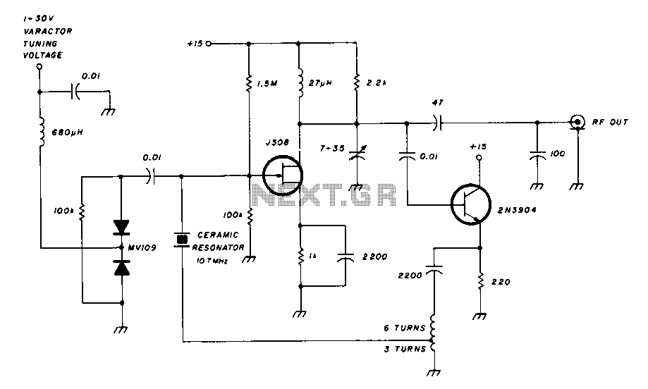
The most important part of this 88-108 transmitter is the Colpitts oscillator. Capacitors C3, C4, C5, C6, diodes CD1 and CD2, and inductor L1 determine the transmission frequency. The RF oscillator... The Colpitts oscillator is a type of electronic oscillator...
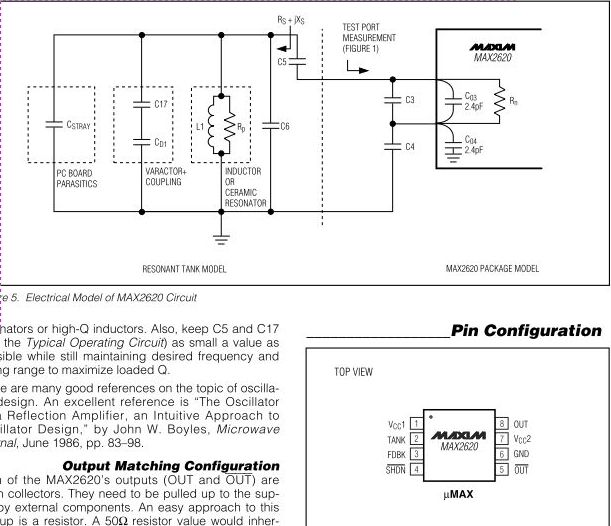
The MAX2620 integrates a low-noise oscillator with two output buffers in a cost-effective, plastic surface-mount, ultra-small uMAX package. This device combines functions that are typically achieved with discrete components. The MAX2620 is designed for applications requiring precise frequency generation with...
The 200 MHz JFET possesses the following characteristics: 1. Low crossmodulation 2. High large-signal handling capability 3. No requirement for neutralization 4. Automatic Gain Control (AGC) managed by adjusting the biasing of the upper. The 200 MHz Junction Field Effect...
A field effect transistor amplifier features a fixed bias input source with feedback, resulting in very high input impedance and low capacitance. It drives a field effect transistor or emitter follower, despite having a very low output impedance, utilizing...
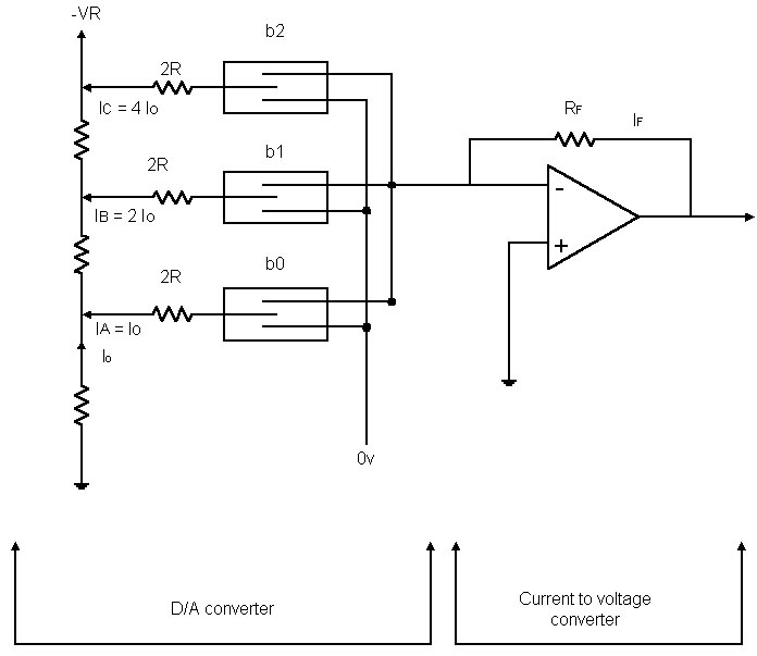
Before examining the various analog-to-digital (A-D) and digital-to-analog (D-A) conversion processes, it is useful to review the properties of each type of representation; in particular, this may help select the representation most suited to the problem at hand. An...
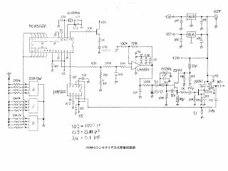
This MOT's LSI is highly suitable for designing VFOs in ham radios, featuring a 4-digit BCD preset counter with a range from 3 to 3999. It also includes a standard crystal frequency oscillator and preset dividers. The input nodes...