
88 108 MHz FM Transmitter Circuit

The Colpitts oscillator is a type of electronic oscillator that generates a sine wave output. In this circuit, it is primarily responsible for producing the radio frequency (RF) signal required for transmission within the 88-108 MHz FM band. The frequency of oscillation is determined by the reactive components in the circuit, specifically the capacitors and inductor.
In this configuration, capacitors C3, C4, C5, and C6 are arranged in a manner that sets the resonant frequency of the oscillator. The values of these capacitors can be adjusted or selected based on the desired transmission frequency within the specified band. The inductor L1 plays a crucial role in resonating with these capacitors, forming a tank circuit that oscillates at a specific frequency.
Diodes CD1 and CD2 are likely used for frequency stabilization or as part of a feedback mechanism that enhances the oscillator's performance. These diodes can also serve to protect the circuit from voltage spikes or to assist in modulating the signal for transmission purposes.
The overall design of the transmitter circuit must ensure that the output signal is clean and stable, minimizing harmonic distortion and unwanted spurious emissions. Proper layout and grounding techniques are essential to maintain signal integrity and reduce noise. Additionally, the use of appropriate shielding can prevent interference from external sources, ensuring compliance with regulatory standards for FM transmission.
In summary, the Colpitts oscillator's design and component selection are critical for achieving reliable and efficient transmission in the 88-108 MHz range, making it a fundamental aspect of the transmitter circuit.The most important part of this 88-108 transmitter is the Colpitts oscillator. C3,C4,C5,C6,CD1-CD2 ans L1 determine the transmission frequency. The RF Osci.. 🔗 External reference
Related Circuits
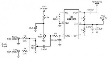
The FM transmitter circuit is built using a single MAX2606 chip. This simple FM transmitter connects a home entertainment system to a portable radio, allowing music to be played in one room and listened to in another, such as...
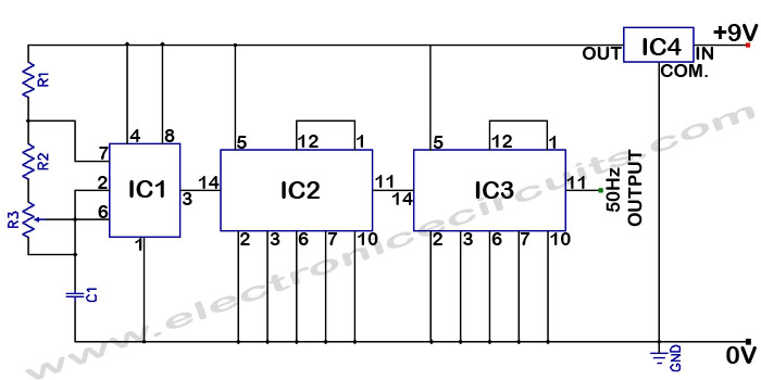
Accurate 50Hz Oscillator Circuit Using 555 and 7490. This circuit generates a 50Hz pulse. It consists of a 555 timer and two 7490 divide-by-ten counters. The circuit utilizes a 555 timer configured in astable mode to produce a square wave...

VU Meter Driver PCB Completed Board Stereo for Two VU Meters Audio Amplifier. VU Meter Driver PCB Completed TA7318P Board Stereo for Two VU Meters Features: Specifications: Power voltage: AC 20V to AC 26V (not more than 26V) size:...
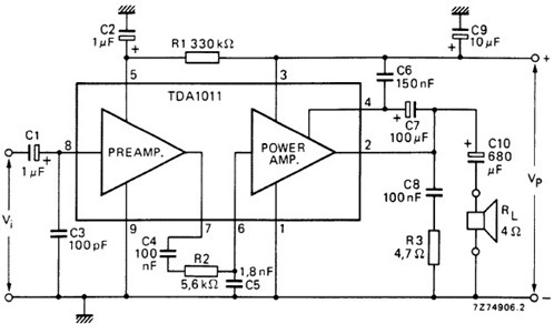
The following schematic illustrates the design of a 4 Watt Amplifier Circuit Diagram intended for portable radio applications, utilizing the TDA1011 integrated circuit from Philips Semiconductor. The 4 Watt Amplifier Circuit is designed to provide audio amplification in portable radio...
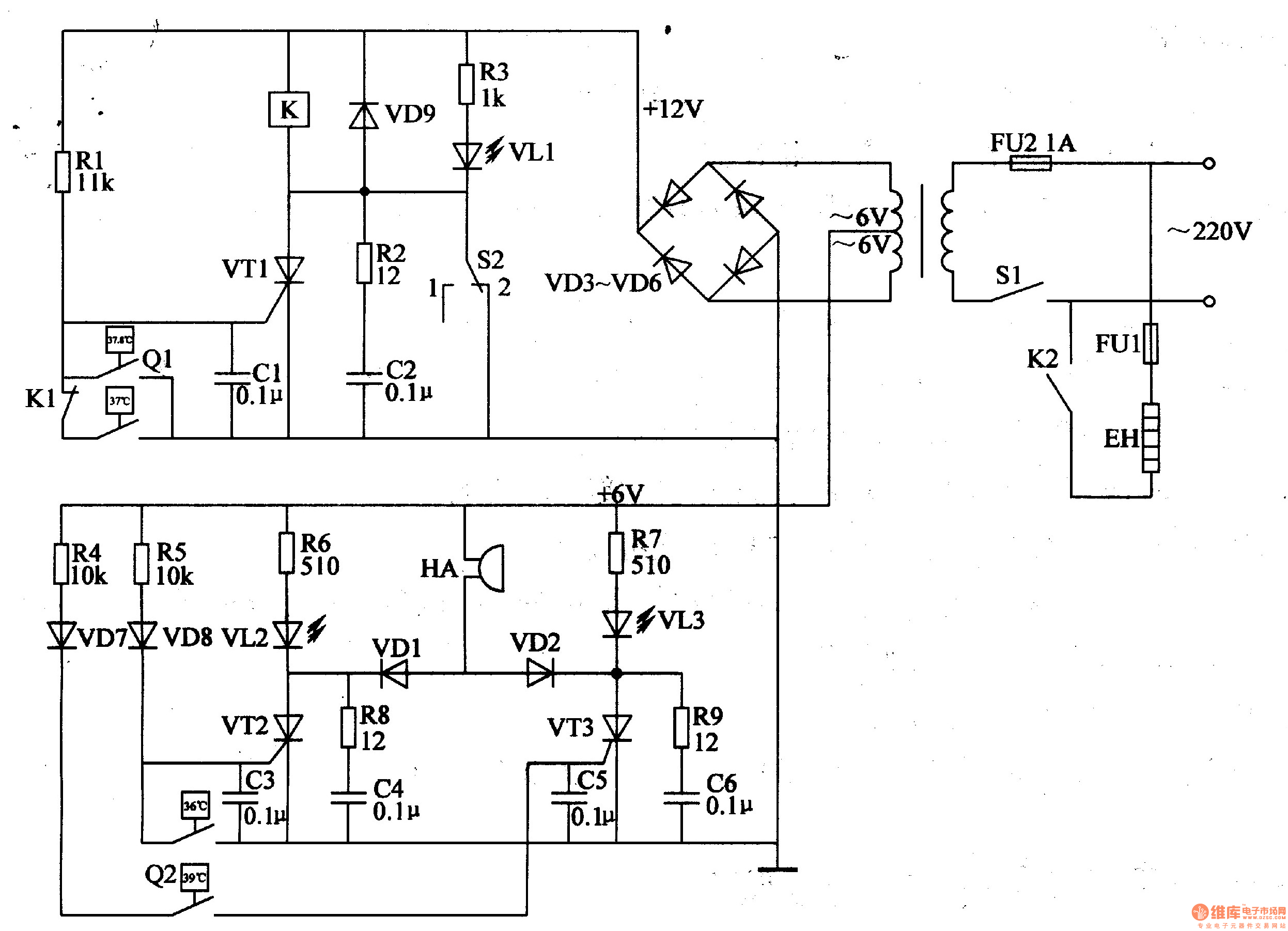
The egg hatching incubator circuit comprises a power supply circuit, a constant temperature control circuit, and a sound and light alarm circuit, as illustrated in Figure 4-7. The power supply circuit includes a power switch (S1), a fuse (FU2),...
All integrated circuits (ICs) are equipped with a 0.1 µF monolithic ceramic capacitor connected across their terminals. Additionally, each board features two capacitors: a 10 µF tantalum capacitor and a 100 µF electrolytic capacitor. The START BUTTON serves as...