
50Hz 60Hz Frequency Generator Circuit Using Crystal Oscillator
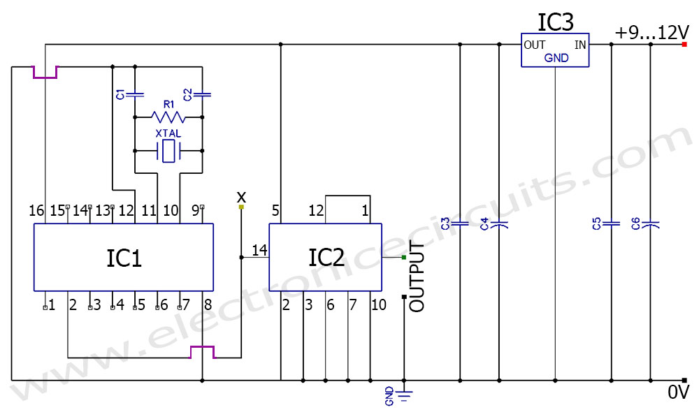
This frequency generator circuit employs a crystal oscillator as its core component, which ensures high stability and accuracy in frequency generation. The circuit is designed to provide selectable output frequencies of 50 Hz and 60 Hz, making it suitable for various applications, including timing circuits, signal processing, and synchronization tasks.
The crystal oscillator operates at a specific resonant frequency determined by the physical characteristics of the crystal used. In this circuit, additional components such as resistors, capacitors, and possibly a flip-flop or a counter may be incorporated to divide the oscillator frequency down to the desired output frequencies.
For instance, if the crystal oscillator operates at a fundamental frequency of 8 MHz, a series of frequency dividers can be used to achieve the necessary division ratios to produce the target frequencies. A common approach is to use a binary counter that divides the input frequency by 160, resulting in a 50 Hz output, or by 133.33 for a 60 Hz output.
The output stage of the circuit may include a buffer or an amplifier to ensure adequate signal strength for driving loads or interfacing with other circuitry. Careful consideration should be given to the power supply requirements, as well as the output impedance, to ensure compatibility with connected devices.
Overall, this frequency generator circuit represents a versatile solution for generating low-frequency signals with high precision, leveraging the inherent stability of crystal oscillators.50 Hz 60 Hz frequency generator circuit using crystal oscillator You can generate 50Hz or 60Hz using this frequency generator. This oscillator.. 🔗 External reference
Related Circuits
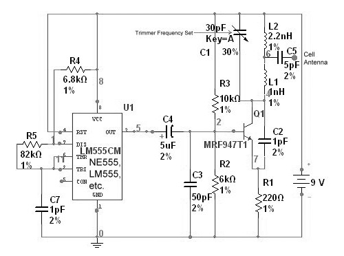
The circuit is based on the NE555 timer, functioning as a simple noise maker, with its output connected to a single transistor oscillator. This oscillator is designed to operate within a frequency range of 800 MHz to 2 GHz,...
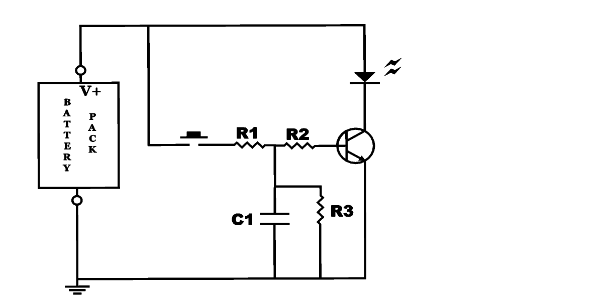
The project involves building an autofade table lamp based on a specific circuit diagram. The actual test circuit is depicted, with a note that resistor R1 from the schematic was omitted, as it was not necessary for the testing...
This is a VU meter analog circuit. The circuit is connected to the line terminals of the amplifier. The VU meter operates simply, with T1 and T2 indicating signal increases. The VU meter circuit is designed to visually represent audio...
The objective is to enhance information transmission through the use of articles. Please contact us via email at [email protected] within 15 days if there are any issues related to article content, copyright, or other concerns. Prompt action will be...
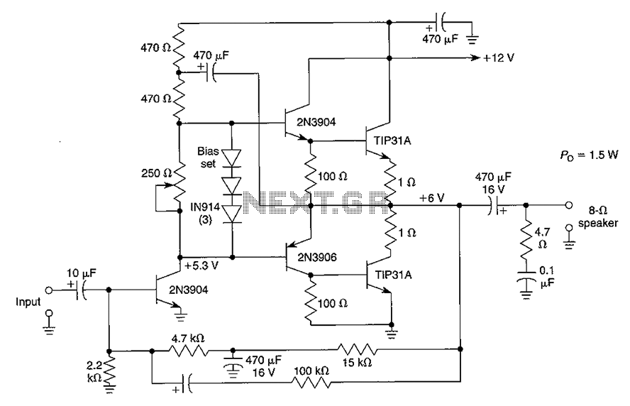
Although the integrated circuit (IC) has largely replaced this circuit, the flexibility of the discrete device design still makes it practical. The components are readily available and cannot easily be eliminated. If desired, a small piece of metal can...
The Magnitude Comparator is a device that compares two 4-bit binary inputs to determine their relationship, indicating whether one input is greater than, equal to, or less than the other. It outputs the conditions A > B, A =...