
Autofade Table Lamp Test Circuit
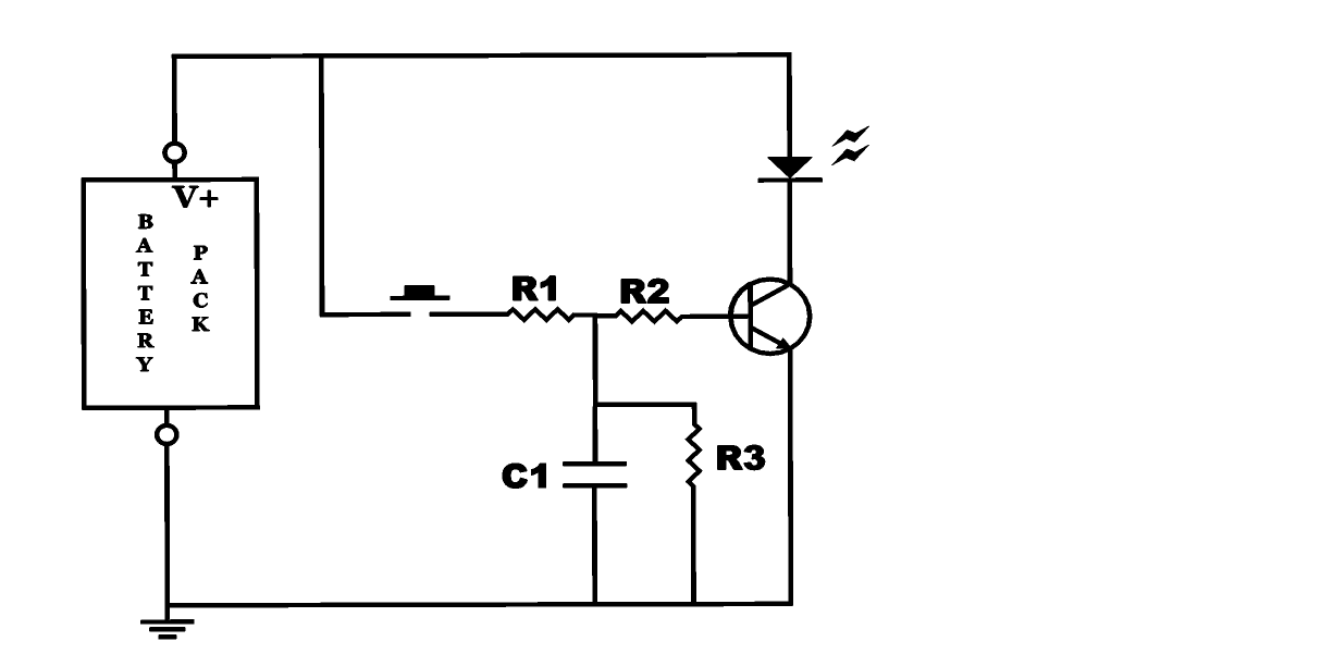
The autofade table lamp circuit is designed to provide a gradual dimming effect when the lamp is turned on or off, enhancing the ambiance of the environment. The core components typically include a microcontroller, a light-emitting diode (LED) or incandescent bulb, a power supply, and several passive components such as resistors and capacitors.
In this circuit, the microcontroller is programmed to control the brightness level of the lamp. It receives input from a user interface, such as a switch or a potentiometer, which allows the user to set the desired brightness level. The microcontroller then adjusts the output signal sent to the lamp, modulating the power supplied to it.
The omitted resistor R1, which is often included in similar circuits for current limiting or stability, may have been deemed unnecessary in this specific implementation. However, its inclusion in other designs can prevent excessive current flow, protecting the LED or bulb from damage.
The power supply provides the necessary voltage and current to the circuit, ensuring that all components operate effectively. Capacitors may be used to smooth out voltage fluctuations, while additional resistors can help in setting the correct operating conditions for the microcontroller and the lamp.
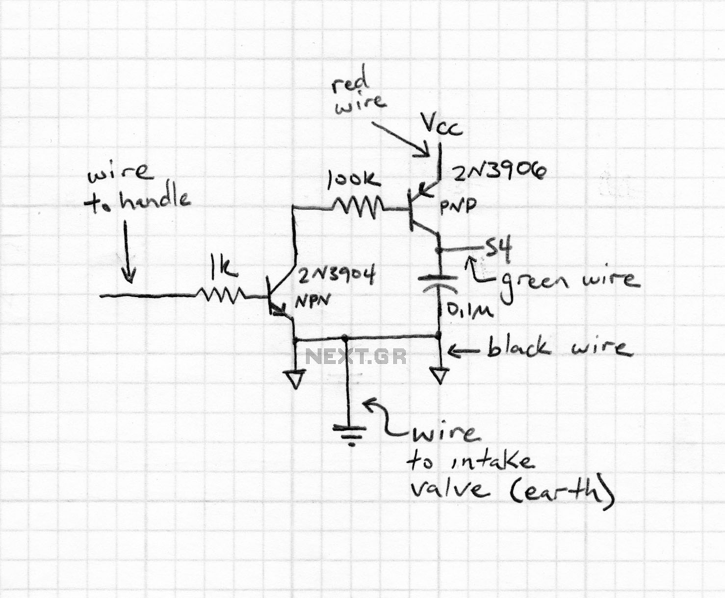
In summary, the autofade table lamp circuit utilizes a microcontroller to create a user-friendly dimming experience, with careful consideration given to component selection and circuit design to ensure reliability and performance.So, as you recall from my previous entry, I wanted to build an autofade table lamp based on this circuit diagram: This is how the test circuit looks in reality (the hand, by the way, is my nephew`s): (Note that resistor R1 in the schematic was omitted in the test circuit. Didn`t need it, turns.. 🔗 External reference
Related Circuits
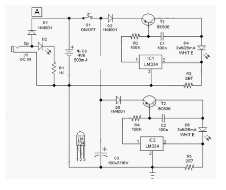
This easy-to-construct "Handy Pen Torch" electronic circuit has a low component count and utilizes two power white LEDs for lighting. It operates on a low voltage supply of 4.8V DC. The Handy Pen Torch circuit is designed to provide a...
The lifespan of a lamp can be prolonged by enhancing the conditions under which its filament operates. This involves eliminating the inrush overcurrent surge and reducing the mechanical stress (vibration) on the filament caused by an AC source. The...

This circuit should be connected prior to the amplifier circuit. To achieve optimal performance, it is recommended to utilize high-quality electronic components such as metal film resistors, MKM capacitors (non-polar), and tantalum capacitors (bipolar). The power supply module can...
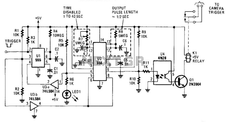
This circuit is designed to activate a camera shutter. Grounding pin 2 of U1 causes pin 4 of U1 to go high, which triggers both timers of the dual timer U1. One output maintains the reset (pin 4) of...
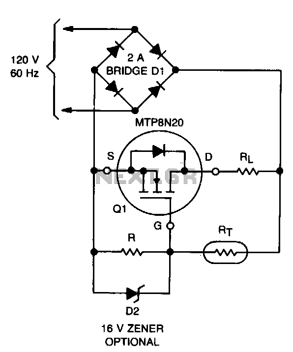
Design a circuit using a power MOSFET to replace the NTC thermistor that many Mag623 users employ to prevent their bulbs from flashing. Although inexpensive and easy to connect, NTCs run quite hot, are affected by ambient temperature, require...
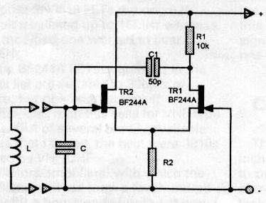
Individuals interested in home construction may occasionally need to measure the inductance of small coils. This task can be challenging, as commercially available equipment with sufficient accuracy is often prohibitively expensive for occasional use in an amateur workshop. Affordable...