
ECE Logic Circuit
The Magnitude Comparator circuit operates by employing a series of logic gates to compare two 4-bit binary numbers, typically represented as A (A3, A2, A1, A0) and B (B3, B2, B1, B0). The outputs are generated based on the comparison results, where three output lines indicate A > B, A = B, and A < B. The circuit can be constructed using AND, OR, and NOT gates, following the logic derived from the truth table created for the comparator.
The Subtractor circuit utilizes XOR gates to perform binary subtraction, where the borrow condition is managed through additional logic gates, ensuring that the subtraction operation is accurately represented in binary form. LED indicators provide a visual representation of the output values, confirming the operation of the subtractor.
For the Seven Segment Display, the circuit is designed to convert the 4-bit binary input into a format suitable for the SSD. The SSD requires specific combinations of inputs to display numbers 0 through 9, and a truth table is essential to map these binary combinations to the corresponding segments of the display. The cathode configuration used in this experiment simplifies the connection process, as the common ground allows for straightforward integration with the output of the IC.
The water level indicator system employs a series of lamps to visually indicate the level of water in a tank. The circuit design requires careful consideration of the truth table to ensure that the correct lamps light up based on the water level. Each lamp corresponds to a specific water level, and the logic for activating these lamps is derived from the system's requirements.
Lastly, the flow rate sensing device utilizes a 5-bit output system to monitor the flow rate in a pipeline. The logical conditions for each output bit are defined based on the flow rate thresholds, and the outputs Y and Z are derived from the simplified Boolean equation. This equation not only aids in the design of the schematic but also ensures that the system functions correctly under varying flow conditions.The Magnitude Comparator is a type of device which compares the two 4 bit binary inputs and determines the output which are the greater than, the equal, and the less than. This device states A>B, A=B, and A
A Seven Segment Display (SSD) is a form of electronic display device for displaying decimal numerals. This is widely used in digital clocks, electronic meters, and other electronic devices. In this activity, we will show how we were able to display decimal numerals (0-9) using binary coded decimal via the SSD.
Before proceeding on, be sure to have an idea how an SSD work and mostimportantlyits pin configuration. Below is an image showing the pin configuration of the SSD. SSD has two types of common. The Cathode and the Anode. The cathode is a common ground while an anode is a common vcc. As for this experiment, we used a cathode, because its common is ground and all our inputs are positive, since an IC produces an output of apositivevalue.
As you can see on the image, there are 7 inputs for this component device. By analyzing thiscomponent, we can use a 4bit binary code (A, B, C, and D). Now that we have our 4bit binary code and our 7 inputs for the display, we can create our truth table. Here is an image of the truth table showing an output of numerical values from 0-9. A water tank system is in need of a level indicator which determines 9 water levels. Ten lamps are used to provide visual indication of the water levels. This is called a water level indicator system which provides the following lamp outputs: Before proceeding in constructing the circuit, let us first analyze the problem statement with the use of the truth table.
Therefore, it would be easy enough to break down the equation step by step. This is the reult from the truth table: Note: If you would like not to have an output with the remaining conditions which are not present on the truth table, convert all the asteries into 0 in order to have a 0 output during the application of the rest of the truth table. This flow rate sensing device is used on a liquid transport pipeline function. This device provides a 5 bit- output in which all the 5-bit becomes 0 of the flow rate is less than 10 gal/min.
The first bit is 1 if the flow rate is at least 10 gal/min. The first and second bit is 1 if the flow rate is 20 gal/min. the first, second and third bit is 1 if the flow rate is at least 30 gal/min and so on. The five bit is represented by A, B, C, D, and E are used as inputs to the device that provides two outputs which is Y and Z. The output Y is 1 if the flow rate is less than 30 gal/min. and the output Z is 1 if the flow rate is at least 20 gal/min but less than 50gal/min. First we Analyze the problem statement given and formulate a Boolean Equation for the system. Then we simplify the equation in any method in which we are comfortable with. The simplified equation would serve as our schematic diagram for the construction of the system. 🔗 External reference
Related Circuits
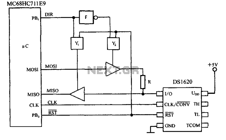
This circuit features a three-wire serial interface for smart temperature sensors, specifically the DS1620, along with an SPI bus interface circuit. The DS1620 is a high-accuracy digital temperature sensor that communicates over a three-wire interface, which consists of a data...
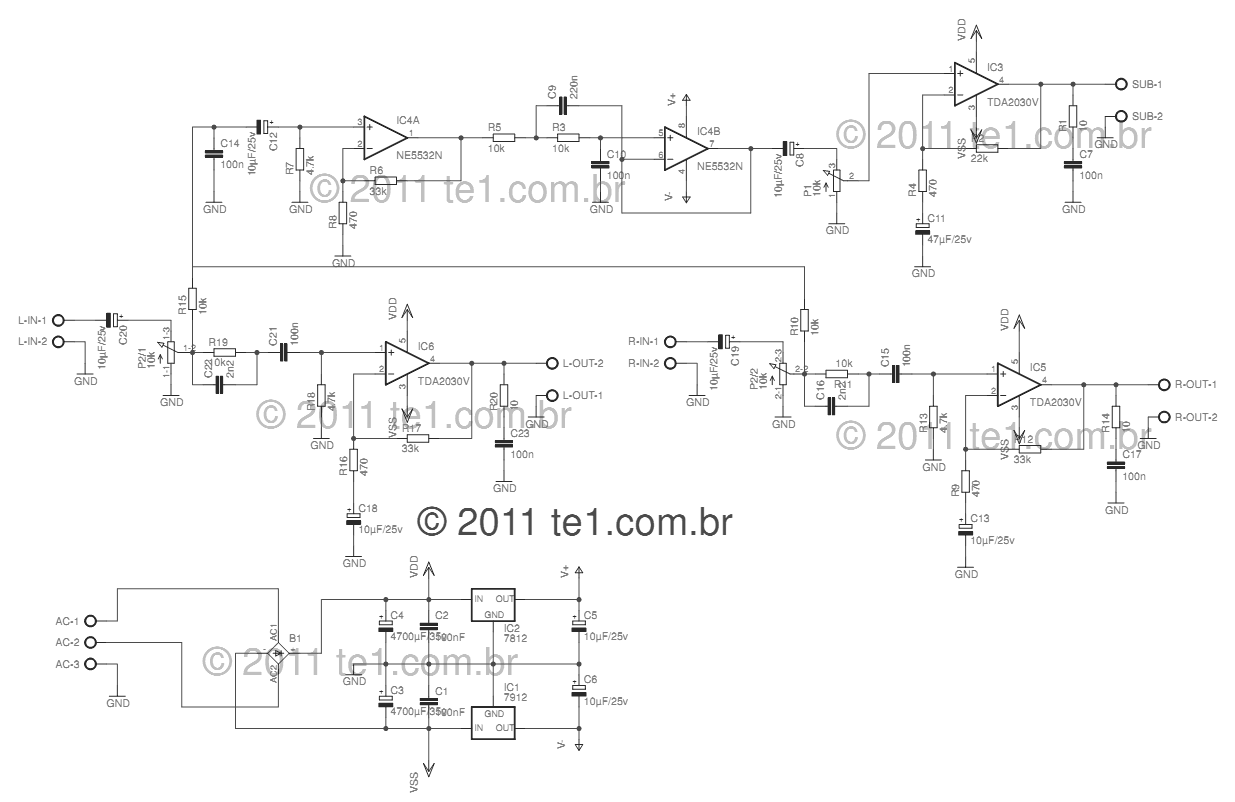
This circuit is a complete application for a 2.1 amplifier system, consisting of two satellite speakers powered by a TDA2030 and one subwoofer. This 2.1 system is commonly utilized in commercial applications as an amplifier for computers, enhancing audio...
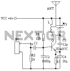
The ordinary triode 3DA87C is utilized to create a long-range FM transmitter circuit, which functions as a standard three-point oscillator circuit. This remote transmitter circuit is capable of large current emissions, achieving a range of up to 1 kilometer...
This schematic illustrates an infrared (IR) transmitter circuit utilizing an integrated circuit (IC). The circuit employs the widely recognized NE555 timer IC, which operates as an astable multivibrator to generate a signal with a frequency of 38 kHz. The...

This schematic diagram illustrates a single-chip Theremin circuit. A Theremin is an electronic musical instrument that detects hand movements to control tones and frequency. The circuit employs two separate Colpitts LC oscillators to generate a beat frequency. The frequencies...
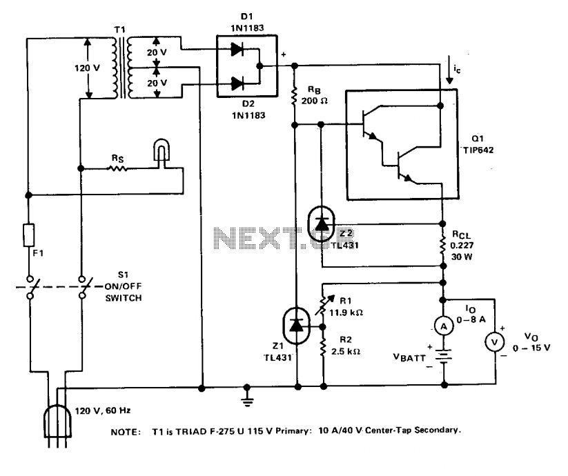
The charger operates with a charging voltage of 2.4 V per cell, aligning with the recommendations of most manufacturers. The circuit delivers a charging voltage of 14.4 V (6 cells at 2.4 V per cell) in a pulsed manner...
Warning: include(partials/cookie-banner.php): Failed to open stream: Permission denied in /var/www/html/nextgr/view-circuit.php on line 713
Warning: include(): Failed opening 'partials/cookie-banner.php' for inclusion (include_path='.:/usr/share/php') in /var/www/html/nextgr/view-circuit.php on line 713