
50hz Calibration aid for Multimeters
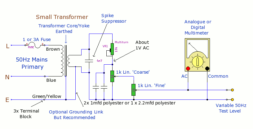
AC feeds a multiturn potentiometer (VR1) that sets the reduced base voltage, which is then connected in series to two tandem-wired 1k linear potentiometers labeled coarse and fine. For ease of adjustment closer to the hole in the box lid, it is recommended that VR1 be mounted on the same tag strip. To enhance the waveform into a more acceptable sinusoidal shape, it can be further low-pass filtered using a single 2.2 μF capacitor or two 1 μF polyester capacitors wired in parallel across the combination of the two pots. The calibrated Avo 8 MkIII test meter, when used, loads the common monitoring line when in the lowest AC range position of 2.5V. However, this loading effect is negligible, as the other multimeter under test will also respond to the same voltage drop. A good, preferably calibrated, multimeter can be connected via 2mm probes to the 2mm meter monitor sockets, while a second meter, if applicable, can be connected to the main output socket, which is a BNC type via adaptors.
Testing begins at high voltages to compare the maximum end of each respective 10V meter display range for accuracy. The Avo is reputed to be more accurate at the high end of its DC and AC scales. Although absolute accuracy of the multimeters under test is not guaranteed at this stage, the coarse and fine pots should be gradually adjusted downward to track the display or scale points together and compare their performance at very low AC voltage and millivolts. It will be noted on the Avo that useful scale resolution ceases at 100mV, while the Beckman multimeter is capable of lower resolution measurements down to millivolts. The testing setup, which includes two meters displaying the same 5V AC readings, indicates an acceptable accuracy level of approximately 95%. This observation raises intriguing questions regarding the performance and reliability of the multimeters being tested.
The schematic design for this prototype unit involves a straightforward configuration where the mains power supply is transformed down to a lower AC voltage suitable for testing. The transformer should be selected based on the required output voltage range, while the resistors in the attenuator allow for fine-tuning of the output voltage. The use of linear potentiometers for coarse and fine adjustments provides a user-friendly interface for precise voltage control. The filtering capacitors play a crucial role in shaping the output waveform, ensuring that the signal remains as sinusoidal as possible, which is essential for accurate multimeter readings.
In summary, this prototype serves as a valuable tool for comparing the accuracy of multimeters across a range of voltages, with careful consideration given to safety, usability, and waveform integrity.The purpose of this prototype unit does away with the need for an oscillator. It offers a mains-derived and fully variable 50 hz AC volts down to millivolts for comparison and to check accuracy, of two or more parallel connected multimeters. Sometimes older instruments of this type are favoured to respond better at low frequencies than higher audi
o frequencies, which are better suited for measurement by wideband audio millivoltmeters. It is to be called to attention that unless otherwise stated by the manufacturer, both mechanical and digital multimeters display all pure and irregular wave shape inputs including square, triangle, sawtooth and integrator, as readings in Mean or Average Form-factor. Obviously the higher the mains transformer secondary voltage output delivered, the higher the AC switched ranges or auto-ranging which can be measured.
The choice of transformer and resistor attenuator values can thus be adapted to suit individual voltage range requirements. Caveat: To comply with Health and Safety, ideally a small adhesive warning sign should be affixed to the box lid to state "Danger Mains Inside".
The prototype does not have one displayed as not being available. However in this case a screwdriver is required to open the lid, therefore that situation is in my control and at my risk. AC feeds a multiturn pot VR1 which sets the reduced base voltage and then in series to two tandem-wired 1k lin pots labelled coarse and fine.
For convenience of adjustment nearer to the hole in the box lid, VR1 is recommended to be supported on the same tag strip. So to improve the waveform to a more acceptable sinusoidal shape, this can be further low-pass filtered by a single 2.
2 mfd or two 1mfd polyester capacitors wired in parallel across the two pots combination as shown. The calibrated Avo 8 MkIII test meter I possess, expectedly loads the commoned monitoring line when in the lowest AC range position of 2. 5v. However this is immaterial as the other multimeter on test also responds to the same volt drop. Connect any good preferably calibrated multimeter to hand, via 2mm probes to the 2mm meter monitor sockets and a second meter if applicable to the main output socket, in this case a BNC type via adaptors.
This test starts at high volts to compare the maximum end of each respective 10v meter display range for accuracy. (The Avo is reputedly more accurate at the high end of its DC and AC scales. ) Though absolute accuracy of the two or more meters under test isn`t guaranteed at this stage, then turn the main coarse & fine pots slowly down to track the display or scales points together and compare their very low AC volts and millivolts performances.
It will be seen on the Avo that useful scale resolution ceases at 100mV, but the Beckman is capable of lower resolution to millivolts. The photo above of two meters on test with the same 5v AC readings, seems to show they have acceptable 95% satisfaction, but it is also intriguing to ponder on this thought-provoking question to finish the article:
🔗 External reference
Related Circuits
Many individuals find that they sleep well in natural environments, such as tents or wooden huts. This phenomenon is attributed not only to the healthy surroundings but also to our subconscious ability to perceive the Earth's natural magnetic fields....
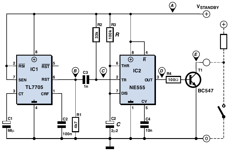
The older PC in question has a standby state but lacks a corresponding BIOS setting to enable unattended startup. Although a +5 V standby supply voltage is present, the computer requires a brief push of a button to power...
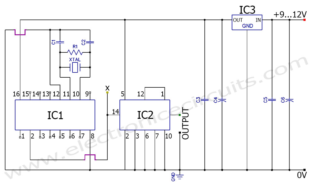
A frequency generator circuit capable of producing 50 Hz and 60 Hz outputs using a crystal oscillator. This oscillator can be utilized to generate precise frequency signals. This frequency generator circuit employs a crystal oscillator as its core component, which...
Convert the smart cards into manual push buttons to control energy consumption, alleviating the consumer's concern about sourcing smart cards, especially given the limited supply in the area. The proposed modification involves replacing the current smart card system with...
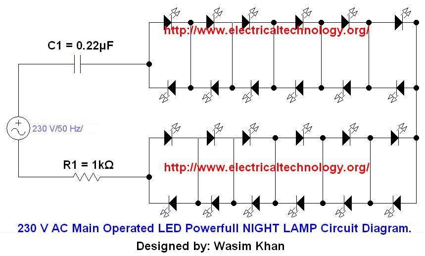
If you plan to use this circuit with a 110V 60Hz supply instead of a 230V 50Hz supply, or if you intend to modify this circuit, please refer to the section titled "Common Questions about this Circuit" found below...
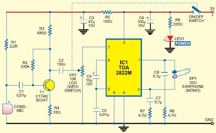
This is a cost-effective DIY option for a hearing aid. It should not be considered a replacement for a genuine hearing aid prescribed by an audiologist. Amplifying all sounds and frequencies, or using it continuously in loud environments, may...
Warning: include(partials/cookie-banner.php): Failed to open stream: Permission denied in /var/www/html/nextgr/view-circuit.php on line 713
Warning: include(): Failed opening 'partials/cookie-banner.php' for inclusion (include_path='.:/usr/share/php') in /var/www/html/nextgr/view-circuit.php on line 713