
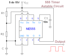
50Khz oscillator

The 50 kHz circuit is designed to operate effectively within that frequency range, leveraging components that exhibit minimal parasitic effects and optimal linearity. The circuit may include elements such as resistors, capacitors, and inductors, carefully selected to ensure that they contribute to the desired frequency response without introducing significant distortion or attenuation.
In such a circuit, the choice of active components, such as operational amplifiers or transistors, is critical. These components should have high gain-bandwidth products, allowing them to maintain performance at higher frequencies. The layout of the circuit board is also essential; minimizing trace lengths and avoiding sharp corners can reduce inductive and capacitive coupling, which can adversely affect circuit performance at 50 kHz.
Additionally, the power supply design is crucial for maintaining stable operation. A well-regulated power supply can prevent voltage fluctuations that may lead to frequency drift or instability. Bypass capacitors should be placed close to the power pins of active devices to filter out high-frequency noise.
Overall, the design of a 50 kHz circuit requires careful consideration of component selection, layout, and power supply management to achieve the nearly ideal characteristics that enable reliable operation at this frequency.A 50 kHz circuit is possible because of the more nearly ideal characteristics. The circuit shown.
Related Circuits
A precision oscillator can be constructed using a quartz crystal; however, with appropriate component selection, it is also possible to build one using an RC (resistor and capacitor) circuit. An RC oscillator generates an oscillating signal through the use of...
A type of relaxation oscillator comprising two stages that are interconnected such that the input of one stage is derived from the output of the other. This configuration essentially consists of two amplifiers cross-coupled with regenerative feedback in its...
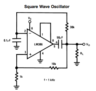
Here is a small LM386-based square-wave oscillator constructed from the following schematic. A 50k potentiometer was used in place of a 30k resistor, which functions as a pitch controller. The audio provided consists of track recordings made in Ableton...
Create an oscillator circuit using an operational amplifier and a 7.68 MHz crystal. The design should be similar to the schematic provided below, but specifically tailored for a 7.68 MHz crystal. The available components include the crystal, various capacitors,...
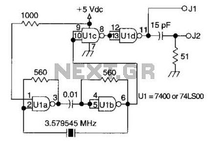
A circuit utilizing one 7400 TTL can operate with fundamental type crystals ranging from 1 to approximately 13 MHz. The output is rich in harmonics, making this oscillator suitable for calibration and testing applications. The circuit in question employs a...
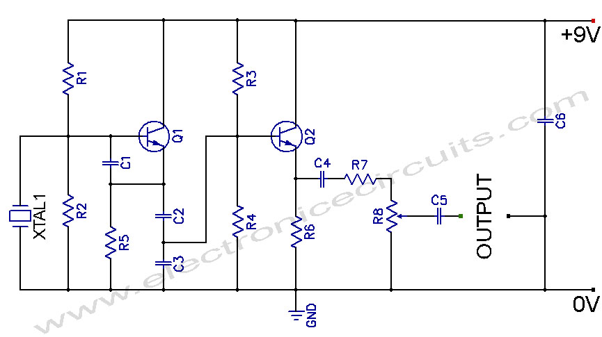
Crystal Controlled Oscillator Circuit. This general-purpose signal source is highly effective in signal-tracing applications. The output level is adjustable. The crystal-controlled oscillator circuit is designed to provide a stable and precise frequency output, which is essential for various electronic applications,...