
555 IC Square Wave Oscillator circuit
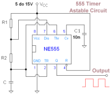
The astable multivibrator configuration using the 555 timer is a versatile tool in electronic design, capable of generating a continuous square wave signal without requiring any external triggering. The oscillation frequency is determined by the values of the resistors (R1 and R2) and the capacitor (C1), which can be calculated using the formula:
\[ f = \frac{1.44}{(R1 + 2R2) \cdot C1} \]
This formula highlights the relationship between the components and the output frequency, allowing designers to select appropriate values based on the desired frequency of operation. The square wave output can be utilized in various applications, including clock pulses, tone generation, and timing applications, making it a fundamental building block in digital circuits.
Additionally, when constructing this circuit, it is recommended to ensure proper power supply decoupling to maintain stability and minimize noise, particularly in sensitive applications. The bypass capacitor connected to the Vcc pin is crucial for filtering high-frequency noise that may affect the performance of the timer.
In summary, the 555 timer configured as an astable multivibrator provides a simple yet effective means to generate precise timing pulses and square wave signals, with adjustable duty cycles and frequencies based on user-defined resistor and capacitor values. This functionality, combined with the ease of integration into various electronic systems, underscores its widespread use in both educational and professional electronic circuits.A form of relaxation oscillator which comprises two stages that are coupled so that the input of one is derived from the output of the other. Basically two amplifiers cross-coupled with regenerative feedback, in it`s most simplistic form. One of the amplifiers is always conducting while the other amplifier is in cut off.In this case both amplifier circuits are contained within a single
555 IC. However the 555 integrated circuit contains a great many transistors. In this case the 555 timer below is configured as an Astable multivibrator with the output having a 50% duty cycle, a square wave [t1 and t2 are equal time periods]. The Astable multivibrator circuit has no stable state. With no external signal applied, the internal transistors alternately switch from cutoff to saturation at a frequency determined by the RC time constants of the coupling circuits.
So an Astable multivibrator is an oscillator which could either be used as a pulse generator or square-wave generator depending on the value of the resistor and capacitors used in the circuit. This particular circuit will produce a 50% duty cycle if R1 is set to 51k ohms and R2 is set to 22k ohms, because the capacitor will charge via R1 and discharge via R2.
The capacitor C1 then sets the frequency of operation. The normally connected 555 acts as a Astable multivibrator but will not generate a 50% duty cycle because the capacitor charges through both resistors but only discharges through one of the resistors. For reference an Astable multivibrator is shown above. Note the difference in resistor connections. A related transistor circuit configured as a Transistor Astable multivibrator. Note that this circuit will not oscillate if RB is greater than 1/2 RA because the junction of RA and RB cannot bring pin 2 down to 1/3 VCC and trigger the lower comparator.
Power: With any integrated circuit always Bypass the Vcc pin to ground via a capacitor, normally a 0. 1uF ceramic capacitor [not shown in the circuit above]. Pin 8 is Vcc and Pin 1 is ground; however the capacitor should be connector to Vcc and taken to the closest ground possible, which may not necessarily be pin 1 of the IC.
The 555 IC may be operated with any voltage between 4. 5 volts and 16 volts, but the output signal level will reflect this. That is, if your interfacing to TTL ICs than the 555 should be power off of 5 volts. Control Voltage: Pin 5 of the 555 is an input and is not used in this application. However is board space allows the control voltage should be bypassed using a 0. 01uF between pin 5 and ground. The capacitor will filter noise on the internal resistor ladder and fix the voltage level on pin 5 so the input does not float to a different voltage. Output: Pin 3 is the output of the circuit. The output will toggle or oscillate between ground and [near] Vcc. With Vcc set at 5 volts the output will switch to a minimum voltage of 2. 75 volts or a typical voltage of 3. 3 volts. Using a 15 volt Vcc as another example the 555 will typically reach 12. 5 volts [200mA source], 13. 3 volts [100mA source]. The rise and fall times of the output pulse will be about 100nS. Trigger: Pin 2 is connected to C1 which develops the voltage to the pin. The Trigger is also connected to the Threshold pin which also sees the same voltage. Threshold: Pin 6 is also connected to C1 which develops the voltage to the pin. The Threshold is also connected to the Trigger pin which also sees the same voltage. Discharge: Pin 7 is connected R2. The capacitor C1 will charge through R1, but will only discharge through R2 into pin 7. This allows for a duty cycle that may be adjusted, because resistors R1 and R2 are not series a 50% duty cycle is possible.
🔗 External reference
Related Circuits
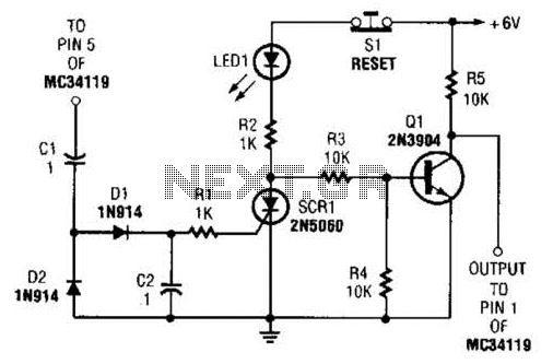
The ear protector is a peak audio detector and shutdown circuit that disables the amplifier through its chip-disable input when the output volume of the amplifier reaches a predetermined level. Although designed for the MC34119 amplifier, the circuit should...
Simple electronics provides the foundation for many closed loop control systems. Since the principle components that we would wish to control for HSP are electronic in nature, an electronic control system is the natural choice. As this document is...
The approaches using on-chip A-to-D converters on AVR, PIC, and Cypress controllers reached sample rates of up to about 60 kHz. Not really very useful for the sort of thing I was thinking about using this for: encoded data,...
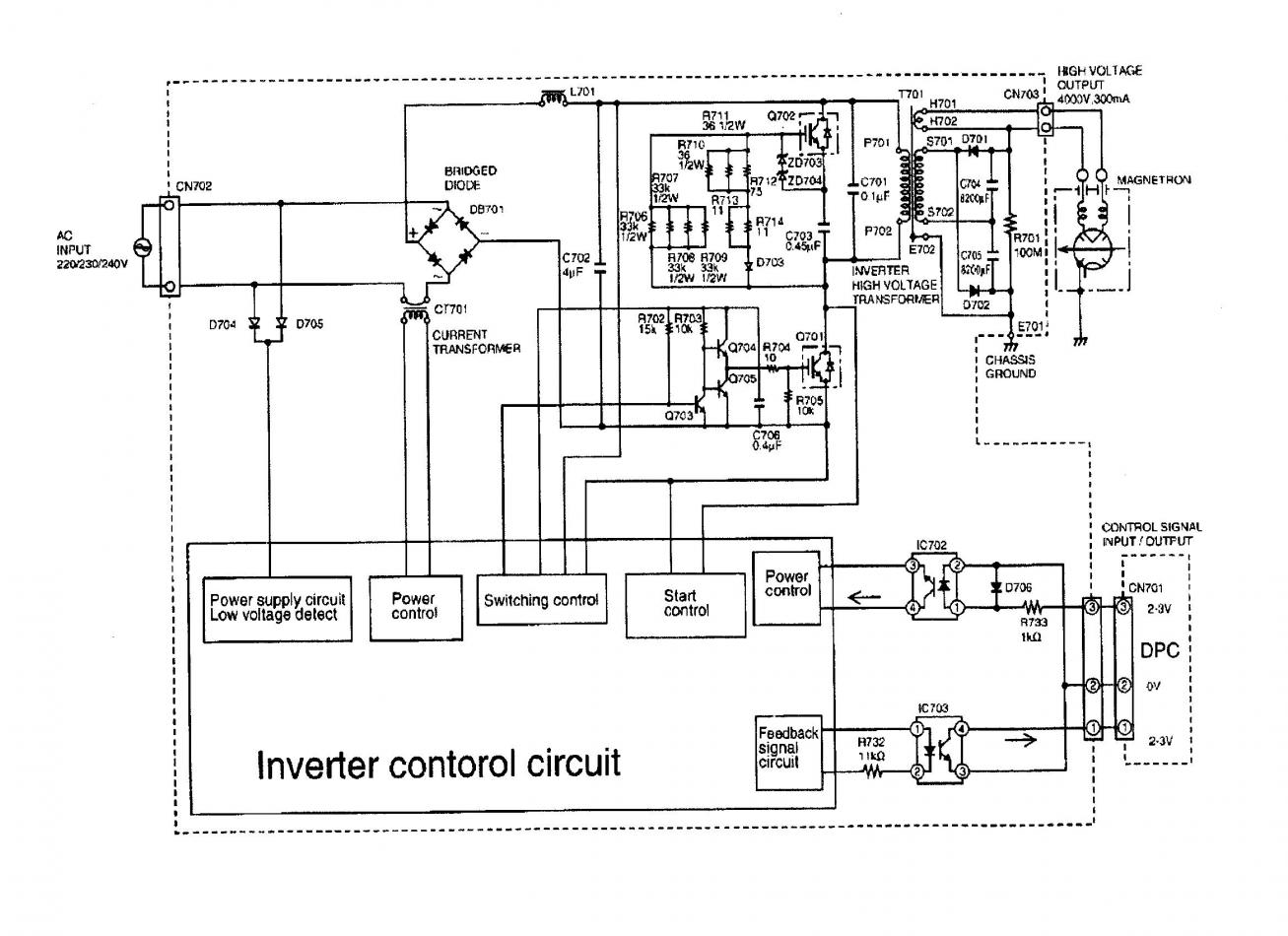
A Panasonic microwave inverter is being utilized for an experimental project. The individual has limited knowledge of electronics but is capable of working on the project. The Panasonic microwave inverter is a sophisticated component designed to provide precise control of...
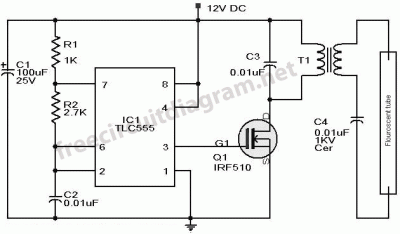
This article presents a driver circuit for a 12V, 5W fluorescent lamp. The circuit utilizes a standard 220V to 10V step-down transformer operated in reverse to achieve a 12V output. The driver circuit for a 12V, 5W fluorescent lamp is...
This device is a highly effective capacitive sensor. In North America, it is primarily utilized for detecting wooden beams behind drywall or plaster. This model is preferred over newer designs due to its reliability, as it does not frequently...
Warning: include(partials/cookie-banner.php): Failed to open stream: Permission denied in /var/www/html/nextgr/view-circuit.php on line 713
Warning: include(): Failed opening 'partials/cookie-banner.php' for inclusion (include_path='.:/usr/share/php') in /var/www/html/nextgr/view-circuit.php on line 713